
Home > HASWILL ELECTRONICS > Haswill Electronics STC-9200 Thermostat User Guide
Haswill Electronics STC-9200 Thermostat User Guide


5. Configurations
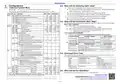
5.2. When will the Defrosting Start / Stop?
5.1. Code and Function Menu
A. Defrost relay will close/on when reaching all the below conditions
⚫
The time should later than: the compressor last stops moment + AC/F05 if the defrosting
Hold the
+
keys at the same time for 10s to enter the Admin Interface;
Mode was thermal air / Hot Gas (TDF/F10 = HTG).
The codes SET and HY (F01 and F02) are user menu; others are admin menu, ref 4.1 A & C
⚫ The defrost sensor temperature < Defrost stop temperature (in DTE/F8)
⚫ Time passed the defrosting cycle time (IDF/F06) or forced defrosting beginning
B. Defrost relay will open/off when reaching any one of the below conditions
⚫ The defrost sensor temperature ≥ Defrost stop temperature (in DTE/F8)
⚫ Passed the defrosting Lasting Time (MDF/F07)
Default
US -5.0
Cate. EN
F
Function
Min Max
Unit
°C
Temp.
SP (Temperature Set-Point)
Temperature Hysteresis / Return Difference
Upper limit for SP
SET F01
HY F02
US F03
LS F04
AC F05
LS
°C
°C
°C
1.0 25.0
2.0
F01 50.0 20.0
-50.0 F01 -20.0
Lower limit for SP
5.3. When will the Compressor Start / Stop?
The room temperature was supposed to keep at the range from " SET/F01" to " SET+HY (F01+F02)."
First, Time Conditions
Delay Time for Compressor
Delay Time for Defrosting (only for hot gas TDF/F10)
Min
0
50
3
Defrost
Cycle / Interval Time
Hour
Min
°C
IDF F06
MDF F07
DTE F08
FDT F09
TDF F10
0
0
120
255
6
A. When FOD/F15 > 0s, the time should be later than:
•
The moment of the compressor recent stops + AC/F05
B. When FOD/F15 < 0s (the fan startup earlier than the compressor), the time later than:
Lasting Time
Defrost
Stop Temperature
Water dripping Time
Defrosting Mode:
30
-50.0 50.0 10.0
10.0
•
•
The moment of the compressor recent stops + AC/F05, and
The fan starts moment + FOD/F15
And Temperature Conditions
Min
0
2
A. If TDF/F10 = EL/0 (like an electric heating wire wound around the evaporator)
N/A
N/A
EL/0 HTG/1 EL/1
RT/0 COH/1 RT/0
Electric-Heating.
EL/0
Controller Status
Forced defrosting
Not in defrosting
Working Condition
Room Temp ≥ SET/F01
The dripping time FDT/F09 is over (ref 4.1 F)
Stops Condition
Room Temp < SET/F01
or defrost beginning
Hot Gas from the compressor.
HTG/1
F11
DCT
Count mode of defrost cycle:
Cumulative time from the controller power on;
RT/0
or forced refrigeration is over.
Room Temp ≥ SET + HY (F01 + F02)
Cumulative time of the compressor working.
COH/1
B. If TDF/F10 = HTG/1 (Hot Gas from the compressor Reverse Rotary), 1 more status than A
F12
DFD
Display mode when defrosting:
Controller Status
Working Condition
Stops Condition
Room Temp < SET/F01;
or defrosting beginning;
or forced Refrigeration is over
and won't defrost at once.
Shows the room sensor temperature display;
Auto defrosting
Evaporator Temp > DTE/F08 defrost stop temp.
RT/0
IT/1
N/A
RT/0
IT/1 RT/1
Shows the evaporator sensor temp. (continue
showing 10 minutes once defrosting over)
Room Temp ≥ SET/F01
The dripping time FDT/F09 is over (ref 4.1 F)
Forced defrosting
Not in Defrosting
Room Temp ≥ SET + HY (F01 + F02)
F13
FNC
Fan
Fan output modes when FOD ≥ 0
CTR/0 Fan Starts by F14/FOT, Stop by F16/FST;
N/A 5.4. Alarming & Error Code
CTR/0 C-N/2 CTR/0
continuous working except defrosting begins;
FOD is when the fan starts later than the compressor;
O-N/1
Once alarming, the readout flashing and buzzer screaming press any key to stop the buzzer ticktack, but the
error code in the display will not disappear until all errors have been fixed.
C-N/2 the fan stops if defrosting begins.
F14
FOT
F15
FOD
Code
E01
E02
HHH
Troublesome From
Room Sensor
Reason
Defrost sensor Temperature for Fan Starts
Time delay seconds for fan
FST/F16
255
°C
S
-50.0
-255
-10.0
60
Open or short
FOD is the period for the fan to start earlier than the
Defrost Sensor
Open or short
< 0
compressor starts; the fan stops before defrosting.
Room or Defrost Sensor
> Max measurable limits 50°C
< Min measurable limits -50°C
≥ 0 The fan was controller by F13/FNC
LLL
F16
FST
F17
ALU
F18
ALL
F19
ALD
FOT/F1
Defrost sensor Temperature for Fan Stops
°C
°C
Readout flash
buzzer screams
Room Sensor
50 °C > room temp. > ALU/F17 or
-50 °C < room temp. < ALL/F18
50.0
-5.0
Alarm
Upper Limit
ALL 50.0 50.0
-50.0 ALU -50.0
Room sensor Temperature
Lower Limit
°C
5.5. When will the Fan Work/Stop?
to Trigger Alarm
0
Time delay
Min
°C
99
-10.0 10.0
15
Please check the conditions from FOD/F15 & FNC/F13 in the menu list.
Cali.
F20
Temperature Calibration = Real Temperature - Measured
OT
0.0
Haswill Electronics https://www.thermo-hygro.com
Copyright Haswill-Haswell All Rights Reserved
The EN code menu and the F code menu are same, just for satisfy different clients.
A
B
C
D
E
F
G
H
I
J
K
L
M N
O
P
Q
R
S
T
U
V
W X
Y
Z
1
2
3
4
5
6
7
8
9 ° C
A B C D E F G H I J K L M N O P Q R S T U V W X Y Z 1 2 3 4 5 6 7 8 9 ° C
2 / 2

| General | Details |
|---|---|
| Name | Haswill Electronics STC-9200 Thermostat User Guide |
| Make | HASWILL ELECTRONICS |
| Language | English |
| Filetype | PDF (Download) |
| File size | 0.24 MB |
 (1 votes, average: 5.00 out of 5)
 Loading...

Haswill Electronics STC-9100 Thermostat User Manual

Haswill Electronics RC-113M PID Thermostat User Guide

Haswill Electronics STC-8080A+ Thermostat User Guide

Haswill Electronics AL8010H Thermostat User Guide

HASWILL ELECTRONICS STC-200 Thermostat User Guide

Haswill Electronics STC-8080H Thermostat User Guide


Futurehome Co020, Co021 Smart Thermostat PR Owner’s Manual

BEOK TDS23 Wi-Fi Thermostat User Manual

SAVANT CLI-W220X-00 Multistat Smart Thermostat User Guide

Danfoss TVM-H Thermostat Valve Owner’s Manual

VIVE TP-S-855C Digital Programmable Thermostat Instruction Manual

tekmar U-T-562 WiFi Thermostat User Manual

hysencontrol HYT001 WIFI Digital Heating Thermostat Instruction Manual

autani 1000172-01 Wave Thermostat Installation Guide

CORDIVARI Stand Alone Control Thermostat for VENTANA Fan Coils User Manual

Mi-Heat GH35EU Digital Greenhouse Thermostat User Manual