BAXI uSense 2 Wired Smart Thermostat Gateway Installation Guide


Give your customers
complete control
Baxi uSense 2 Wired Smart Thermostat Gateway Installation guide

| General | Details |
|---|---|
| Name | BAXI uSense 2 Wired Smart Thermostat Gateway Installation Guide |
| Make | BAXI |
| Language | English |
| Filetype | PDF (Download) |
| File size | 0.41 MB |


BAXI uSense 2 Wired Smart Thermostat Installation Guide

BAXI uSense 2 Wired Smart Thermostat Gateway Installation Guide Overview
Summary of Contents
- Page 1: Give your customers complete control. Baxi uSense 2 wired smart thermostat. Gateway installation guide.
- Page 2: Compatibility In the box Before you start Installation OpenTherm hot water control (combi only) Outdoor sensor Technical specifications Gateway LED key Warning: High voltage wiring must only be installed and worked on by a suitably qualified person.
- Page 3: Compatibility This Gateway & Power Adapter Kit is only required for certain products in the Baxi range. The Baxi uSense 2 Wired Smart Thermostat is compatible with all appliances using the 230 V switched live and also has OpenTherm and RBUS capability. The Baxi uSense 2 Smart Room Thermostat is compatible with all Baxi, Potterton & Main Combi boilers. Baxi Air Source Heat Pumps (ASHP) may also require an additional uSense 2 Gateway & Power Adapter Kit Accessory. Baxi uSense 2 is Boiler Plus Compliant when fitted via OpenTherm or RBUS connection. For multiple zones, a Baxi uSense 2, Gateway & Power Adapter Kit is required for each zone. This control is not compatible with System or Heat Only Boilers.
- Page 4: Gateway package includes various components. The installation guide provides necessary instructions. Screw and plug fixings are included for setup. A 230V power adaptor is part of the package. An adhesive pad for the power adaptor is also provided.
- Page 5: Before you start Wear appropriate personal protection equipment, e.g. protective gloves, safety footwear. Positioning the uSense 2 should consider several factors, including: - On an internal wall - 1.5 m away from draughts - 1.2-1.5 m from the floor - Not behind doors, bookcases, or other objects - Not in direct sunlight - In a room where the user spends most of their time - Away from heat sources (fireplace, radiators, light, candles, etc.) The maximum cable length from the gateway to the room unit is 50 m. Prior to installation, ensure to isolate the power to the heating and control system and make safe (remove or lock off fuse). Check that the power has been isolated using suitable test equipment. Warning: High voltage wiring must only be installed and worked on by a suitably qualified person.
- Page 6: Installation The gateway When connecting the gateway to an appliance that has an existing programmer and/or thermostat, it is essential that the function of all wiring is established prior to work. Make sure you identify the L (live), N (neutral), E (earth), common and call for heat switched live correctly before connecting. Incorrect wiring will result in damage to the gateway, room unit and appliance which will invalidate the warranty. Determine the position of the gateway. It should be close to either the appliance or control system junction box. Make sure there is enough space around the gateway for installation and maintenance, including screwdriver access.
- Page 7: Run power to the gateway. Use the power adaptor supplied to connect the gateway to the L (live) and N (neutral) connectors on the appliance or junction box. Connect the plugged end of the power adaptor into the 24 V terminal on the gateway. All cables must be supported. The power adaptor and wiring must not be inside the appliance. The power adaptor must be supported (adhesive pad is supplied for this). 24 V OT R-BUS ON/OFF.
- Page 8: Installation of 230 V switched connection Connect the system control wiring to the gateway. To connect using the ON/OFF terminals, connect the common from the appliance or junction box to the ON terminal. Read in conjunction with the appliance installation and service manual on the gateway. Connect the switch live terminal or junction box to the OFF terminal on the gateway. The cable used must be 0.75 mm multi strand flexible cable conforming to BS 50525-2-11. Gateway terminals - ON/OFF are for 230 V switching. Gateway terminals - OT are for OpenTherm connection to compatible appliances. Gateway terminals - R-BUS are for connection to the uSense room unit. These components are low voltage - 230 V will damage the room unit and gateway. Please see diagram on page 7.
- Page 9: Installation of OpenTherm connections To connect using the OT terminals Connect the OpenTherm connectors on the appliance to the OT terminals on the gateway. Do not connect 230 V to these OpenTherm terminals or it will damage the gateway. These will communicate with the appliance to control the heating and other functions. These connections can be made using bell wire. There is no polarity at the OT terminals.
- Page 10: To connect the gateway to the uSense 2 using the R-BUS terminals Choose a suitable location for the uSense 2 thermostat. Remove existing thermostat if applicable. Fix the room unit backplate to the wall using the screws provided. Either use existing thermostat wires or run new wires from the gateway. There is no polarity - either wire can be connected to either position. Trim the wires coming out of the wall. Connect them into the connector block on the room unit backplate.
- Page 11: Slacken the screws at the sides of the connectors and insert each wire into the top at either side of the connector, then re-tighten the screws. Make sure the wires are as flat as possible against the back plate so that they do not interfere with the controller when it is mounted in position. Press the room unit onto the backplate until it clicks into place. Connect the other end of the wires to the R-BUS terminals in the gateway (there is no polarity - either wire can be connected to either position). The connection between the room unit and gateway is low voltage; 230 V will damage the room unit and gateway.
- Page 12: Set up the uSense 2 room unit. Before turning on the power to the gateway, room unit and heating system, preliminary electrical tests should be carried out. These should be carried out using a suitable meter, and include checks for earth continuity, resistance to earth, short circuit and polarity. Turn on the power to the gateway and check that the gateway and room unit power up. Download the Baxi Thermostat App and create a uSense account.
- Page 13: OpenTherm hot water control The uSense 2 room unit will override the hot water temperature controls on your appliance. The room unit will automatically default the hot water temperature to 60 °C when connected by OpenTherm. The room unit will automatically default the heating flow temperature to 80 °C when connected by OpenTherm. These settings can be adjusted to your required comfort level using the uSense 2 room unit only.
- Page 14: Outdoor sensor Connecting to an outdoor sensor If an outdoor sensor weather compensator is connected in conjunction with the uSense, you can only adjust the heating curve on the Baxi Thermostat App. Open the Baxi Thermostat App. Click on the installer menu. Click on advanced settings. Enter service code 0012. Remember to re-enter this code to disable installer access when you finish adjusting the heating curve. Change the curve to suit the requirements of the user in accordance with the recommendations of the sensor manufacturer. Do not adjust any other settings in the Advanced Feature menu, as they may affect the correct operation of the appliance. Either completely close the App or re-enter the code to cancel the access level.
- Page 15: Technical specifications uSense 2 room unit Dimensions: Width x height x depth (maximum dimensions) Power supply: 24 V ± 5% Maximum power consumption: 1.5 W Maximum cable length for dedicated room unit R-Bus: 50 m Storage temperature: -25 to 70 °C Relative humidity: 5 - 95% (condensation is not allowed) Operating conditions: 0 - 60 °C
- Page 16: uSense 2 room unit Technical data Room temperature measurement range Maximum temperature deviation at 20 °C Maximum room control overshoot after pre-heating Temperature variation Outside temperature Temperature control area Refer to appliance documentation
- Page 17: Compliant with standards: EMC: 108/2004/EC, EN 55022, 55014 Immunity: EN 26-61000 ETSI-EN 17-489 301 R&TTE Directive 5/1999/EC EN 160950 (ITE - Safety - Part 1: general requirements) Low voltage directive (95/2006/EC) WEEE directive (96/2002/EC) (disposal requirements) Drop test: IEC 32-2-60068 Protection classification: IP 22 ErP Fiche Information
- Page 18: Gateway Temperature input 24 V, 4 W R-BUS 24 V, 100 mA Max. 70 W 30 VDC 230 VAC 4.0 compliant 0 °C - 60 °C ON/OFF OpenTherm Insulation class IP 21
- Page 19: Gateway LED key The LED on the gateway indicates the following modes and faults: Starting up Gateway in operation No appliance detected (check connections and wiring) No room unit detected (check connections and wiring) Internal error (turn all power off, reinstate and perform setting procedure again)
- Page 20: Page 20

Eurotronic Technology sprit Z-Wave Smart Radiator Thermostat Installation Guide

Drayton Wiser Smart Room Thermostat Instruction Manual

PRO1 R250W Wireless System Thermostat Owner’s Manual
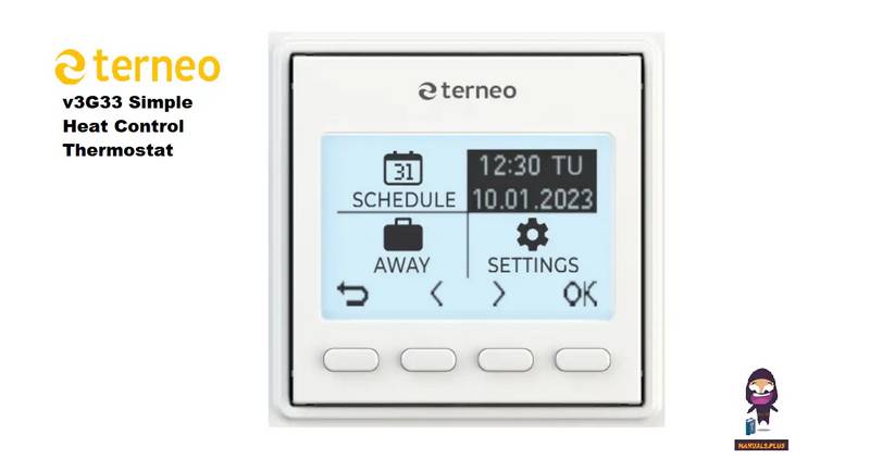
terneo v3G33 Simple Heat Control Thermostat Instruction Manual

GENERAL LIFE SENNA 270S Digital Room Thermostat User Manual

SIEMENS Powers Controls TH 192-3 Series Day Night Vent Room Thermostat Instruction Manual

GENERAL Life ARUNA 300S RF Wireless Room Thermostat User Guide

AeoTec Radiator Thermostat ZWA021 User Manual

WHITE-RODGERS 1F90-71 5-Day 2-Day Electronic Digital Thermostat Instruction Manual

Rheem RETST700SYS EcoNet Smart Thermostat Owner’s Manual