Honeywell T834 Series Thermostat Owner’s Manual


Owner’s Manual
English: Page 1
Mode d’emploi
Français: Page 6
Manual de Uso
Español: Página 11
T834 Series
Thermostat
This manual covers the following models:
Horizontal Mount: T8034N • Vertical Mount: T834N/T834L
Pre-installation checklist
Check package contents:
Before you begin, make sure you have:
•
•
Thermostat
Wall anchors & screws (2 each)
•
•
•
•
•
No. 2 Phillips & small pocket screwdrivers
Hammer
Level (optional)
Pencil
Drill and bit (3/16” for drywall, 7/32” for plaster)
Must be installed by a trained, experienced technician
•
Read these instructions carefully. Failure to follow these instructions can
damage the product or cause a hazardous condition.
CAUTION: ELECTRICAL HAZARD
Can cause electrical shock or equipment damage. Disconnect power before
beginning installation.
MERCURY NOTICE
If this product is replacing a control that contains mercury in a sealed tube, do not
place the old control in the trash. Contact your local waste management authority for
instructions regarding recycling and proper disposal.
® U.S. Registered Trademark. Patents pending.
Copyright © 2006 Honeywell International Inc.
All rights reserved.
firealarmresources.com

| General | Details |
|---|---|
| Name | Honeywell T834 Series Thermostat Owner’s Manual |
| Make | Honeywell |
| Language | English |
| Filetype | PDF (Download) |
| File size | 0.56 MB |


Honeywell T6 Pro Programmable Thermostat User Manual

Honeywell D1-528 Direct Thermostat Installation Guide

Honeywell FocusPRO P200 Programmable Thermostat User Guide

Honeywell RCHT8610WF Series Smart Thermostat Installation Guide

Honeywell T9 Smart Thermostat Installation Guide

Honeywell TH2320WF4011 FocusPRO Smart S200 Series Thermostat User Guide

Honeywell TL116A Thermostat Installation Guide

T10 Pro Smart Thermostat with Redlink Room Sensor

Honeywell TH6320WF2003 Lyric T6 Pro Wi-Fi Programmable Thermostat User Guide

Honeywell RTH9580 Wi-Fi Color Touchscreen Programmable Thermostat User Guide

Honeywell T834 Series Thermostat Owner’s Manual Overview
Summary of Contents
- Page 1: Owner’s manual This manual covers the following models: Pre-installation checklist Check package contents: Before you begin, make sure you have: Must be installed by a trained, experienced technician Read these instructions carefully. Failure to follow these instructions can damage the product or cause a hazardous condition. CAUTION: Electrical hazard can cause electrical shock or equipment damage. Disconnect power before beginning installation. MERCURY NOTICE: If this product is replacing a control that contains mercury in a sealed tube, do not place the old control in the trash.
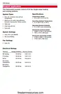
- Page 2: T834 Series This thermostat provides control of 24 Vac single-stage heating and cooling systems. Specifications Temperature range: 50° to 90°F (10° to 32°C). Operating ambient temperature: 0° to 120°F (-18° to 49°C). Operating relative humidity: 5% to 90% (non-condensing). Dimensions (vertical model): 2.88W x 4.75H x 1.5D (inches). System settings: Heat, Off, Cool (T834N); Off, Cool (T834L). Dimensions (horizontal model): 4.75W x 2.88H x 1.5D (inches). Fan settings: Auto, On. Electrical ratings: Voltage (50/60Hz) for heating and cooling is 20-30 Vac.
- Page 3: Base installation involves pulling wires through the wire hole, positioning the base on the wall, and marking hole positions. Drill holes for wall anchors and pull wire through the base before tightening mounting screws. Wiring requires loosening screw terminals, inserting bare wires beneath screws, and then re-tightening screws. Excess wire should be pushed back into the wall opening, which should be plugged with nonflammable insulation to prevent drafts. Terminal designations include R for heating power, Rc for cooling power, G for fan relay, W for heat relay, B for heat pump changeover valve in heating, O for heat pump changeover valve in cooling, and Y for compressor contactor. For heat pump systems, a small piece of wire is needed to connect terminals W and Y. Use 18-gauge thermostat wire; shielded cable is not required.
- Page 4: T834 Series Set fan switch (except model T834L) Fan operation settings: For gas or oil heating systems, leave the fan operation switch in this factory-set position. Change the switch to this setting for heat pump or electric heat systems. Set heat anticipator (except model T834L) Move the adjustment arrow to the proper setting for your system. Thermostat mounting Align the slots on the cover with tabs on the sides of the base, then push gently until the cover snaps into place.
- Page 5: Operation Fan switch System switch On: Fan runs continuously. Cool: Controls the cooling system. Heat: Controls the heating system. Off: All systems are off. Auto: Fan runs only when heating or cooling system is on. Temperature setting: Adjust to set desired indoor temperature. Caution: Equipment damage hazard. Do not operate cooling system when outdoor temperature is below 50°F (10°C). 5-year limited warranty. Honeywell warrants this product to be free from defects in workmanship or materials for a period of five years from the date of purchase.
- Page 6: Owner’s Manual Thermostat Employez ce manuel pour les modèles suivants : Modèle Horizontal : T8034N Modèle Vertical : T834N / T834L Éléments nécessaires à l’installation Vérifiez le contenu de paquet : Outillage et matériel nécessaires : Il est impératif de faire réaliser l’installation par un technicien chevronné Lisez attentivement les présentes consignes. La non observation de celles-ci risque d’endommager le produit ou de présenter des dangers. MISE EN GARDE : RISQUE ÉLECTRIQUE AVIS CONCERNANT LE MERCURE
- Page 7: Application du produit Ce thermostat est prévu pour réguler des systèmes de chauffage et de climatisation à une zone de 24 V ca (secteur). Caractéristiques Types d’installations Chauffage au gaz, au mazout ou électrique avec climatisation Fourchettes de température 50° à 90° F (10 à 32° C) Température d’expédition 0° à 120° F (-18° à 49° C) Humidité relative de fonctionnement 5% à 90% (sans condensation) Dimensions (modèle vertical) 2.88”W x 4.75”H x 1.5”D Réglages du mode Heat, Off, Cool (T834N) Dimensions (modèle horizontal) 4.75”W x 2.88”H x 1.5”D Caractéristiques Électriques Tension (50/60Hz) 20-30 Vca
- Page 8: T834 Series Montage de la plaque Tirez les fils par l’ouverture de la plaque. Placez la plaque sur le mur, mettez-la à niveau et marquez la position des trous. Percez des trous, puis enfoncez les chevilles. Placez la plaque sur les chevilles, introduisez et serrez les vis de montage. Câblage Desserrez les bornes à vis, insérez les fils nus sous des vis, puis resserrez les vis. Rentrez les fils qui dépassent dans l’ouverture du mur. Bouchez l’ouverture du mur avec de l’isolant ininflammable pour empêcher les courants d’air de perturber le fonctionnement du thermostat. Désignation des bornes R Alimentation chauffage. Raccorder au côté secondaire du transformateur de l’installation de chauffage. R c Alimentation climatisation. Raccorder au côté secondaire du transformateur de l’installation de chauffage. Bornes R et Rc Dans une installation à transformateur unique, laissez le cavalier en métal en place entre les bornes R et Rc. Retirez le cavalier en métal dans le cas d’une installation à deux transformateurs. G Relais du ventilateur. W Relais de chauffage. B Valve d’inversion de la thermopompe mise sous tension en mode chauffage. Installations à thermopompes En cas de câblage à une thermopompe, raccordez les bornes W et Y par un petit morceau de fil (non fourni). Caractéristiques du fil Utilisez du fil à thermostat de calibre 18. Il n’est pas nécessaire d’utiliser du fil blindé. Y Contacteur du compresseur.
- Page 9: Ajustez le commutateur de ventilateur (excepté T834L). Options pour le ventilateur : Pour les installations à gaz ou à mazout, laissez le commutateur dans la position usine. Amenez le commutateur dans cette position dans le cas d’une thermopompe ou d'une installation de chauffage électrique. Ajustez le détecteur de la chauffage (excepté T834L). Déplacez la flèche à l'arrangement approprié pour votre système. Votre système : vapeur, chauffage d'eau chaude, air chaud (à haute efficacité), air chaud (standard), air chaud électrique. Montage du thermostat. Alignez les fentes du couvercle avec les languettes du thermostat. Poussez doucement jusqu’à ce que le couvercle s’emboîte en place.
- Page 10: T834 Series Mode d’emploi Commutateur de ventilateur Mode de fonctionnement On : Le ventilateur fonctionne en permanence. Cool : Régule que la climatisation. Heat : Régule que le chauffage. Off : Tous les systèmes sont éteints. Auto : Le ventilateur ne fonctionne que lorsque le chauffage ou la climatisation sont en marche. Réglage de la température : Ajustez pour obtenir la température intérieure désirée. MISE EN GARDE : RISQUE D’ENDOMMAGER LE MATÉRIEL. Ne pas faire fonctionner la climatisation lorsque la température extérieure est inférieure à 50° F (10° C). Garantie limitée de cinq ans Honeywell garantit ce produit contre tout vis de fabrication ou de matière dans des conditions d’utilisation et de service normales, pendant une durée de cinq (5) ans à compter de la date d’achat par le consommateur. Cette garantie vous donne des droits spécifiques face à la loi et vous pouvez en avoir d’autres, variables d’un état à un autre.
- Page 11: Owner’s Manual This manual covers the following models: Horizontal Model: T8034N Vertical Model: T834N / T834L Pre-installation checklist Check the package contents: Necessary tools and materials: - Phillips screwdriver No. 2 - Small pocket screwdriver - Hammer - Level (optional) - Pencil - Thermostat - Wall mounts and mounting screws (2 each) - Drill bit (3/16” for masonry, 7/32” for drywall) It must be installed by a qualified and experienced technician. Read these instructions carefully. Ignoring them could damage the product or create hazardous conditions. Caution: Electric hazard May cause electric shock or equipment damage. Disconnect power before starting installation. Mercury notice If this product replaces a control containing mercury in a sealed tube, do not throw the old control in the trash. Contact local waste disposal authority for recycling and proper disposal instructions.
- Page 12: T834 Series Aplicación del producto Este termostato brinda control de los sistemas de calefacción y refrigeración de una sola etapa de 24 VCA. Especificaciones Tipos de sistemas Rangos de temperatura Calefacción a gas, petróleo o eléctrica con aire acondicionado 50° a 90°F (10° a 32°C) Humedad relativa de funcionamiento 5% a 90% (sin condensación) Dimensiones (modelo vertical) 2.88W x 4.75H x 1.5D (inches) Ajustes del sistema Dimensiones (modelo horizontal) 4.75W x 2.88H x 1.5D (inches) Ajustes del Ventilador Auto, On
- Page 13: Instalación de placa de montaje Tire de los cables a través de su orificio. Posicione en la pared la placa de montaje, nivélelo y marque las posiciones de los orificios. Coloque la placa de montaje sobre los soportes, inserte y ajuste los tornillos de montaje. Cableado Afloje los terminales atornillados, inserte los alambres pelados debajo de los tornillos y vuelva a ajustar los tornillos. Empuje el exceso de cable de vuelta en la abertura de la pared. Tape la abertura de la pared con aislamiento no inflamable para evitar que las corrientes de aire afecten el funcionamiento del termostato. Designaciones de terminales R: Alimentación de calefacción. Rc: Alimentación de refrigeración. W: Relé de calefacción. B: Válvula de cambio del bombeo de calor activada durante la calefacción. Y: Contactar del compresor. Use cable de termostato calibre 18.
- Page 14: T834 Series Ajuste de funcionamiento del ventilador (excepto T834L) Opciones del ventilador: Para los sistemas de calefacción a gas o petróleo, deje el interruptor de funcionamiento del ventilador en la posición original de fábrica. Cambie el interruptor a esta posición para los sistemas de calefacción eléctricos o de bombeo de calor. Ajuste el anticipador del calor (excepto T834L). Mueva la flecha al ajuste apropiado para su sistema. Montaje del termostato. Alinee las ranuras de la cubierta con las lengüetas del termostato.
- Page 15: Instrucciones de manejo Interruptor del ventilador El ventilador funciona continuamente. Controla el sistema de refrigeración. Controla el sistema de calefacción. Todos los sistemas están apagados. Funciona sólo cuando está encendido el sistema de refrigeración o calefacción. Resbale para fijar temperatura deseada. Cuidado: peligro de daño al equipo. Garantía limitada de cinco años. Honeywell garantiza que este producto no tendrá defectos de fabricación ni de materiales durante cinco años a partir de la fecha de compra.
- Page 16: Need help? For assistance with this product please visit the Honeywell website or call Honeywell Customer Care toll-free. Automation and Control Solutions Honeywell International Inc. Patents pending. All rights reserved. Printed in China. © 2006 Honeywell International Inc.

vtech T961NN50 Universal Wired Thermostat User Guide

COMPUTHERM Q5RF Multi Zone Wireless Digital Room Thermostat Instruction Manual

seitron Wi-Time Wall Wi-Fi Programmable Thermostat Instruction Manual

AIRZONE Blueface Zero Thermostat User Manual

TPECO Control Systems 375EM Raintight Weather Resistant Single Stage Thermostat Instruction Manual

PRINCESS 01.171017.01.001 Fondue Premium Thermostat Instruction Manual

DEVI 610 Electronic Thermostat Installation Guide

tecnoswitch EN60730-1 Electronic Recessed Thermostat User Guide

Danfoss RET Series Electronic Thermostat Instruction Manual

Honeywell Smart Color Touchscreen Programmable Thermostat RTH9590 User Manual