
STELPRO ST252NPFF Non-Programmable Electronic Thermostat Owner’s Manual
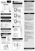


INITIAL SETTINGS
OWNER’S
MANUAL
CONNECT THE POWER
SUPPLY WIRES
2
To begin with, follow the on-screen instructions to adjust your
thermostat’s settings. Press
to confirm.
or
to change your selection and
WARNING: Incorrectly connected electrical wires could
result in a fire hazard.
NON-PROGRAMMABLE ELECTRONIC THERMOSTAT
FOR BASEBOARDS, CONVECTORS AND FAN HEATERS
• Temperature format: °C / °F (Celsius / Fahrenheit)
• ECO mode setpoint temperature: (5°C to 30°C / 41°F to 86°F).
By default, the ECO mode setpoint is 17°C / 63°F.
1. Complete the thermostat’s electrical connection according to
the diagram below. Tighten the wires securely in the supplied
wire connectors.
ST252NPFF ST402NPFF
Your heating needs may vary according to the season and even
the time of day. To meet your needs, this thermostat is equipped
with two distinct modes: ECO and COMFORT. You can switch from
2. Push the wires and connectors into the electrical box.
one mode to another by simply pressing
you money by providing a more energy-efficient setpoint tempera-
ture when you’re sleeping or away from home.
. ECO mode saves
NOTE: If the electrical wires are aluminum, use CO/ALR connec-
tors instead (not supplied).
• Heating mode: (Baseboard / Fan heater)
FOR BASEBOARDS, CONVECTORS AND FAN HEATERS
• Lobby mode: STD / LBY (Standard room / Lobby).
In LOBBY mode, the thermostat automatically provides 100%
heating for five minutes as soon as a sudden drop in temperature
is detected. This mode can be useful for heaters located near
an entrance. When this mode is activated, the
icon flashes.
LOBBY mode is available only if the heating mode selected is
“Fan heater.”
1-844-STELPRO
WWW.STELPRO.COM
B
L1=Black
ER
L2/N=Red
LD=Yellow
YELLOW
The diagram shows a 240 V power supply.
FEATURES
FOR BASEBOARDS AND CONVECTORS ONLY
IMPORTANT INSTRUCTIONS
KEY FEATURES
1. Press
or once to lower or raise the setpoint temperature by
THE THERMOSTAT MUST BE INSTALLED BY A CERTIFIED
ELECTRICIAN.
0.5°C / 1°F. The setpoint temperature will remain at this value
until it is changed.
Connect the thermostat to a 120 to 240 VAC power source ONLY and
comply with load limits.
NOTE: If you change the setpoint temperature while in ECO mode,
the thermostat will switch to COMFORT mode.
WARNING – HIGH VOLTAGE. Turn off the power supply before
installation and maintenance. Leave at least 12 in. (30 cm)
clearance around the thermostat to ensure that it is properly
vented.
B
2. Press
once to switch from ECO mode to COMFORT mode
and vice versa.
L1=Black
ER
YELLOW
3. Press and
simultaneously to activate BOOST mode
or to select BOOST mode duration
L2/N=Red
. Then, press
LD=Yellow
The diagram shows a 240 V power supply.
(10, 20, 30, 40, 40, 50 or 60 minutes). The thermostat will then
heat at 100% for the time specified. When BOOST mode is on,
the time remaining is displayed on the screen.
SAVE THESE INSTRUCTIONS
FOR BASEBOARDS AND CONVECTORS ONLY
4. Press any button to discontinue BOOST mode.
TECHNICAL SPECIFICATIONS
VOLTAGE AND LOAD
PRODUCT CODE
SUPPLY VOLTAGE
LOAD AT 120 V
LOAD AT 240 V
ADVANCED MENU ACCESS AND USE
VOLTS
WATTS
WATTS
ST252NPFF
ST402NPFF
150-1250
150-2000
300-2500
300-4000
1. Press and hold
advanced menus.
for 3 seconds to access the thermostat’s
120-240
B
2. Press
or to change your selection.
Load control type
Frequency
Resistive
60 Hz
3. Press
menu.
to confirm your selection and proceed to the next
L1=Black
Storage temperature
-40°C to 50°C (-40°F to 122°F)
L2/N=Red
LD=Yellow
YELLOW
-20°C to 50°C (-4°F to 122°F).
LC display less effective below 0°C (32°F)
The diagram shows a 240 V power supply.
Operating temperature
4. Press and hold
for 3 seconds to exit the advanced menus.
Humidity
5% to 98% without condensation
ADVANCED MENUS LIST
Action
Type 1.Y
• 10 – Temperature format: °C / °F (Celsius / Fahrenheit)
Pollution degree
Software
2
Class A
• 20 – ECO mode setpoint temperature (5°C to 30°C / 41°F to
86°F). By default, the ECO mode setpoint is 17°C / 63°F.
Rated impulse voltage
Category II overvoltage (1500 V)
ATTACH THE THERMOSTAT
3
Independently mounted control for surface mounting
Thermistor used as a sensor, carries no load current
• 30 – Load type selection (Convector / Fan heater). FAN HEATER
mode is the default mode.
Overload protection device external to the control: circuit breaker (refer to local electrical code)
• 31 – Lobby mode: STD / LBY (Standard room / Lobby). LOBBY
mode is available only if the heating mode selected is
FAN HEATER.
1. Using the alignment guide,
hook the bottom [A] of the
thermostat into the bottom of
the plate. Be sure not to jam
the wires between the thermo-
stat and mounting plate.
BEFORE YOU GET STARTED
• 40 – Keypad lock: ON / OFF (Lock keypad / Unlock keypad)
• dEF – Reset thermostat to default values: N / Y (No / Yes)
• The box contains one (1) thermostat with mounting plate, two (2)
mounting screws, three (3) twist-on wire connectors and one (1)
owner’s manual.
2. Rotate the thermostat upwards
and attach it on the top hook of
the mounting plate.
• To install this thermostat, you will need a #2 Phillips screwdriver.
USING THE TECHNICAL MENUS:
• Install your thermostat about 5 ft (1.5 m) from the floor on an
inside wall facing the heating system.
1. Press
menus (the advanced menu will appear after 3 seconds but
continue to hold for another 7 seconds).
for 10 seconds to access the thermostat’s technical
A
B
3. Tighten the screw at the top of the
thermostat [B] to hold it in place
securely.
2. Use
ou to change your selection.
3. Press
menu.
to confirm your selection and continue to the next
INSTALLATION
4. Restore the power at the circuit
breaker.
4. Press
menus.
for 3 seconds to exit the thermostat’s technical
TECHNICAL MENU LIST
NOTE: If you need to remove the
thermostat, follow step 1 in section
1, then use a straight screwdriver
to unhook it from the top of the
mounting plate.
ATTACH THE MOUNTING PLATE
1
• t1: Maximum room temperature setpoint limit
(5°C to 30°C / 41°F to 86°F). The default setting is 30°C.
• t2: Minimum room temperature setpoint limit
(5°C to 30°C / 41°F to 86°F). The default setting is 5°C.
A
WARNING: Turn off the
power supply.
NOTE: The maximum setpoint limit must be higher than the mini-
mum setpoint limit, and the minimum setpoint limit must be lower
than the maximum setpoint limit.
1. Loosen the screw [A] at the
top of the thermostat without
removing it.
INTERFACE
• t3: Year of production
• t4: Month of production
• t5: Identification number
• t6: Software version
2. Separate the mounting plate
from the thermostat. Pull the
top of the plate and rotate.
This is a NON-PROGRAMMABLE thermostat. The temperature
setpoint remains constant unless you change it.
MOUNTING
PLATE
Touch the keypad once to activate the backlight, then you can
make changes.
• t7: Thermostat control code
3. Take the power wires [B] out of the junction box and
run them through the large opening in the center of the
mounting plate [C].
Heating output
4. Using the two (2) mounting screws provided [D], attach the
thermostat mounting plate to the junction box. The plate
can be centered on the junction box or shifted to the left
or right.
Mode aéroconvection
(Le mode VESTIBULE est
en action s’il clignote)
Keypad locked
Ambient
temperature/
contextual
B
information
Menu indicator
Current menu*
ECO mode
indicator
D
C
Keypad
JUNCTION BOX
STELPRO LIMITED WARRANTY
D
MOUNTING PLATE
*Displays only when using the advanced menus.
STELPRO DESIGN INC. Saint-Bruno-de-Montarville, Québec, Canada, J3V 6L7


| General | Details |
|---|---|
| Name | STELPRO ST252NPFF Non-Programmable Electronic Thermostat Owner’s Manual |
| Make | StelPro |
| Language | English |
| Filetype | PDF (Download) |
| File size | 0.4 MB |
 (1 votes, average: 5.00 out of 5)
 Loading...

STELPRO STF362NP Floor Heating Thermostat Owner’s Manual

STELPRO ST302P Programmable Electronic Thermostat Owner’s Manual

STELPRO SAT402ZB Smart Thermostat User Guide

STELPRO ST402PFF Programmable Electronic Thermostat Owner’s Manual

STELPRO ASMC402 Maestro Zigbee Smart Programmable Thermostat User Guide

STELPRO SIBTE12C Electronic Thermostat Owner’s Manual

STELPRO STZW402+ Electronic Thermostat for The Smart Home Owner’s Manual

STELPRO SIBTE13F Electronic Thermostat User Guide

STELPRO STCP MULTIPLE PROGRAMMING ELECTRONIC THERMOSTAT User Guide

STELPRO STCP Floor Heating Thermostat Multiple Programming User Guide

Stelpro ST252NPFF Manual: Questions and Answers
What is the default ECO mode setpoint temperature for the Stelpro ST252NPFF?
17°C / 63°F. Owner's Manual, p. 1
How do I attach the thermostat to the mounting plate?
Use the alignment guide to hook and rotate the thermostat into place.
- Hook the bottom of the thermostat into the bottom of the mounting plate, avoiding jamming wires
- Rotate the thermostat upwards and attach it to the top hook of the mounting plate
- Tighten the screw at the top of the thermostat to hold it securely Owner's Manual, p. 1
Other Stelpro ST252NPFF manuals
More Stelpro thermostat manuals

SALUS Wired Digital Thermostat – Non-programmable HTRS230 User Manual

ESi ESRTP4 TOUCH Programmable Room Thermostat Instruction Manual

BEOK CONTROLS TDR89 ZIGBEE Thermostat User Guide

Honeywell CM721 Programmable Room Thermostat User Guide

Sygonix 2735095 Wireless Indoor Thermostat Instruction Manual

Honeywell TH8321U Touch Screen Programmable Thermostat Installation Guide

TOUPWELL TP808 WiFi Low Voltage Thermostat User Guide

klima SF300 Thermostat User Manual

Honeywell Smart Color Touchscreen Programmable Thermostat RTH9590 User Manual

Decdeal HY607 WIFI Digital Heating Thermostat User Manual