Home > SALUS > SALUS RT310 Thermostat User Manual

SALUS RT310 Thermostat User Manual

RT310 (HEAT/COOL) THERMOSTAT - FULL USER MANUAL  
GeneralDetails
NameSALUS RT310 Thermostat User Manual
MakeSALUS
LanguageEnglish
FiletypePDF (Download)
File size0.6 MB
Download PDF
1 Star2 Stars3 Stars4 Stars5 Stars (1 votes, average: 5.00 out of 5)
Loading...
SALUS IT800 WIFI Smart Thermostat Installation Guide
SALUS 091FLRF Wireless Room Thermostat User Guide
SALUS Thermostat Sensor TS600 User Guide
SALUS Thermostat and Smart Plug Installation Guide
SALUS Wired Thermostat Installation Guide
SALUS Wired Digital Thermostat – Non-programmable HTRS230 User Manual
SALUS RT520 Radiator Thermostat User Guide
SALUS Programmable Wired Thermostat VS30W/VS30B Installation Guide
SALUS Thermostat RT520 User Manual
SALUS BTR230 Room Thermostat User Guide

SALUS RT310 Thermostat User Manual

Get the free PDF manual for the SALUS RT310 Thermostat User Manual and access setup steps, usage instructions, and troubleshooting tips. 👉 View online or download now to keep your thermostat running smoothly!

SALUS RT310 Thermostat User Manual Overview

Summary of Contents

  • Page 1: The document appears to be a user manual for the RT310 heat/cool thermostat.
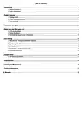
  • Page 2: Introduction Product compliance Safety informations Product overview Package content Proper thermostat location Wall mounting Connection description Before you start (first power up) LCD icon description Button description First power up sequence and configuration User settings Manual mode - changing temperature setpoint Frost protection mode Sleep mode Heat/Cool mode Temperatures outside operating range Low battery detection Installer mode DIP switches parameters Reset function Cleaning and maintenance Technical informations Warranty
  • Page 3: Product overview The RT310 room thermostat switches the heating system on and off as necessary by sensing the air temperature. Turning a room thermostat to a higher setting does not make the room heat up faster. The speed at which the room heats up depends on the design of the heating system. Setting the thermostat to a lower temperature saves energy. To find a comfortable temperature, set the thermostat to a low temperature and increase it by one degree each day. Any adjustment above the comfortable setting will waste energy and cost more money. Typically, there is only one room thermostat to control the whole house, but thermostatic radiator valves (TRVs) can allow for different temperatures in individual rooms. Room thermostats require a free flow of air to function properly and should not be obstructed. Product advantages include a TPI control algorithm and adjustable hysteresis settings. The thermostat features frost protection mode and a SLEEP mode for energy efficiency.
  • Page 4: Wall mounting Content used for thermostat mounting How to mount the thermostat to the wall: Fix the backplate to the wall. Align the front housing at the top edge. Fit the front housing. Press lightly. You can also use a flush mount housing and a German and UK wall box to mount the thermostat directly into the wall. The standard wall box has a diameter max 60mm and depth from 41-46 mm. The cable entry on the backplate must allow a cable with 2*1,5 mm.
  • Page 5: Connection description AC 230V Legend: Symbols explanation: L, N - power supply 230V NO, COM, NC - voltage-free output Boiler - Boiler connection Boiler’s contacts for ON/OFF thermostat (according to the boiler’s instructions) Pump Valve actuator
  • Page 6: Before you start (first power up) LCD icon description Heating mode indication Cooling mode/frost protection mode indication Low battery status Temperature unit Room/setpoint temperature RF signal indicator (only in RT310RF) Button description Turn on the LCD backlight HEAT/COOL modes change or frost protection mode activation (only when HEAT mode is enabled)
  • Page 7: First power up sequence and configuration To power up the thermostat, you have to put the batteries inside. Remove the protection foil and insert 2xAA batteries by removing the front cover. After that, the thermostat will automatically power up and display all icons. The thermostat will display the software version. When the thermostat is successfully powered up, the main screen will be displayed.
  • Page 8: User settings Manual mode - changing temperature setpoint In manual mode, the thermostat maintains a constant temperature set by the user. To set temperature setpoint follow steps below: Press or to set the new temperature setpoint. First, thermostat is displaying actual room temperature. Now wait 2 seconds timeout to approve the changes. Thermostat will display main screen (actual room temperature) and flame icon will start flashing (calling for heating in HEAT mode).
  • Page 9: Frost protection mode automatically sets the temperature to prevent pipes from freezing. If the room temperature is below the frost setpoint, frost protection is enabled. To activate frost protection, press the button to turn it ON/OFF. The snowflake icon indicates that frost protection is active. The frostpoint temperature can be reviewed but only changed in Installer Mode. Frost protection mode can only be enabled in HEAT mode. Sleep mode turns off the thermostat, preventing energy consumption and any actions until reactivated. To activate sleep mode, press and hold the designated buttons simultaneously for 3 seconds. In sleep mode, the thermostat's display is blank. To deactivate sleep mode, press any button to return to the main screen.
  • Page 10: Heat/Cool mode allows the user to set the thermostat for heating or cooling. In HEAT mode, the thermostat displays a flame icon continuously. When in HEAT mode and calling for heat, the flame icon flashes. In COOL mode, the thermostat displays a snowflake icon continuously. When switched to COOLING mode and calling for cool, the snowflake icon flashes. The default mode is HEAT mode. There may be a delay of about 3 minutes when starting to call for cooling. To set cooling mode, press and hold the snowflake button for 5 seconds. To set heating mode, press and hold the snowflake button for 5 seconds. When switched to HEATING mode, the flame icon is steady on.
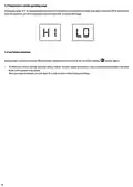
  • Page 11: Temperatures below 10 °C are displayed without the leading ‘0’. Temperatures exceeding the measurable range will be indicated by ‘HI’ for temperatures above the upper limit, and ‘LO’ for temperatures below the lower limit. Battery voltage is checked every minute. When the battery voltage drops to a certain level, the low-battery warning indicator appears. The thermostat functions normally during low battery. User must change the batteries as soon as possible before the battery is too weak for normal operation. When you change the batteries, you have about 30 seconds to do so without losing your settings.
  • Page 12: Installer mode To enter installer parameters, follow the steps below. Refer to the parameters table description before making any changes. Press and hold buttons simultaneously for about 3 seconds to enter the installer mode. Use buttons to move through parameters. Use buttons for adjustments. Confirm every change/selection by pressing the button. Detailed table with all installer parameters: Temperature display accuracy: Temperature offset options are 0.1°C or 0.5°C, with a default of 0.5°C. Frost protection setpoint temperature ranges from 5.0°C to 17.0°C. DIP switches are used to set the chosen control algorithm and are located under the back cover of the thermostat. The position of the DIP switches determines the type of control algorithm for cooling and heating. TPI algorithm is recommended for underfloor heating and can be adjusted between a low comfort level (6 CPH) and a higher comfort level (9 CPH).
  • Page 13: Reset function To reset the RT310 thermostat, press the reset button once using a paper clip. Your thermostat will be reset and will start up automatically.
  • Page 14: Cleaning and maintenance of the RT310 thermostat requires no special maintenance. The outer casing can be wiped clean using a dry cloth. Do not use solvents, polishes, detergents, or abrasive cleaners. There are no user serviceable parts within the unit. Servicing or repairs can only be carried out by Salus Controls or their appointed agents. Technical information includes a power supply of 2 x AA batteries. The rating max is 3(1) A. The output signal is NO/COM/NC relay. The temperature range is 5 - 35°C. Display temperature accuracy is 0.1°C or 0.5°C. The control algorithm can be TPI or hysteresis. The dimensions are 96 x 96 x 27 mm.
  • Page 15: Warranty information outlines that SALUS CONTROLS guarantees the product against defects in material or workmanship for five years from the installation date. The company is responsible for repairing or replacing defective products. The warranty includes software that corresponds to the distributor's identification at the time of sale. The manufacturer's warranty covers all functions and specifics of the product as marked. The warranty does not cover the operation of functions resulting from software updates. Full warranty conditions can be found on the SALUS CONTROLS website.
  • Page 16: Distributor of Salus Controls: QL Controls Sp. z o.o., Sp. k. Importer: Salus Controls Plc Salus Controls is a member of the Computime Group. Maintaining a policy of continuous product development, Salus Controls plc reserve the right to change specification, design and materials of products listed in this brochure without prior notice. Ver. 6 Issued: 11 XII 2020 Soft version: 2.1