
SALUS Digital Room Thermostat RT310/RT310RF Installation Guide
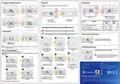


Button functions
DIP switches parameters
Default
value
RXRT510 Receiver
RT310 / RT310TX Thermostat
ON
1
2
Cooling
Heating
Span
9CPH
0.25°C
Model: RT310 (Digital room thermostat)
RT310RF (Digital room wireless thermostat)
ON ON Hysteresis +/- 0.25 °C Hysteresis +/- 0.25°C
1
2
3
4
ON ON
ON OFF
Hysteresis +/- 1.5°C
Hysteresis +/- 1.0°C
Hysteresis +/- 0.5°C
TPI 9 CPH
6CPH
TPI
1
2
OFF OFF Hysteresis +/- 0.5°C
TPI 6 CPH
5
7
6
8
RT310 Wiring diagram
1. Turn on the LCD backlight
2. HEAT/COOL modes change
or Frost Protection mode
activation
5. When in Manual Mode,
ON will turn the boiler on
6. When in Manual Mode,
OFF will turn the boiler of
AC 230 V
L
3. Increase button
4. Decrease button
7. Receiver operates in automatic mode
according to the thermostat
MAX
3 (1) A
8. Receiver output is controlled
by the On/Off slide switch.
LCD Icon description
or
M
Installation Manual
1. Heating Mode ON
2. Cooling Mode ON/
Frost Protection Mode ON
3. RF signal indicator (only in RT310RF)
4. Low battery status
1
2
3
4
5
6
N
RT310RF Wiring diagram
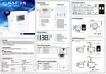
Introduction
5. Temperature unit
6. Room / setpoint temperature
Note: If you are using the RT310RF pack, the pairing between the thermostat and the receiver
is already done!
RT310 / RT310RF is a digital room thermosat used to control room temperature. Device launching
heating or cooling system by shorting terminal blocks, simultaneously informing the action and
showing this information on the LCD display. Before use please read this manual carefully. Use only
AA 1.5 V alkaline batteries in the thermostat. Place the batteries into the battery slot located under the
cover. Do not use rechargeable batteries.
AC 230 V
L
RT310 Terminals description
Product compliance
Directives: EMC 2014/30/EU, LVD 2014/35/EU, RED 2014/53/EU and RoHS 2011/65/EU.
L
Terminal
1 - COM
2 - NC
Description
Common Terminal
Switched Live OFF
Switched Live ON
COM
NO
N
Safety Information
3 - NO
Use in accordance to national and EU regulations. Use the device as intended, keeping it in dry condition.
Product for indoor use only. Installation must be carried out by a qualified person in accordance to
national and EU regulations.
N
AC 230 V
L
Technical specification
RT310
RT310RF
RXRT510 Receiver terminals description
Thermostat supply
Receiver supply
2 x AA alkaline batteries
2 x AA alkaline batteries
COM
L
Terminal
NO
Description
-
230 V AC
-
MAX
16 (5) A
Switch Terminal
Thermostat rating max
Receiver rating max
3 (1) A
-
N
NO
COM
Common Switch Terminal
Supply (230 V AC)
16 (5) A
NO COM
L
N
L, N
Voltage free
NO / COM /NC terminals
Voltage free
NO / COM terminals
Outputs
or
M
5 - 35°C
5 - 35°C
N


| General | Details |
|---|---|
| Name | SALUS Digital Room Thermostat RT310/RT310RF Installation Guide |
| Make | SALUS |
| Language | English |
| Filetype | PDF (Download) |
| File size | 0.26 MB |
 (1 votes, average: 5.00 out of 5)
 Loading...

SALUS IT800 WIFI Smart Thermostat Installation Guide

SALUS 091FLRF Wireless Room Thermostat User Guide

SALUS Thermostat Sensor TS600 User Guide

SALUS Thermostat and Smart Plug Installation Guide

SALUS Programmable Wired Thermostat VS30W/VS30B Installation Guide

SALUS Wired Thermostat Installation Guide

SALUS Wired Digital Thermostat – Non-programmable HTRS230 User Manual

SALUS RT520 Radiator Thermostat User Guide

SALUS RT310 Thermostat User Manual

SALUS Thermostat RT520 User Manual

Salus RT310/RT310RF Manual: Questions and Answers
What is the difference between heating and cooling mode on the Salus RT310/RT310RF?
In heating mode the flame icon shows. In cooling mode the snowflake icon displays and the thermostat adds a 3-minute delay before reporting a cooling demand.
| Mode | Display Icon |
|---|---|
| Heating | Flame icon |
| Cooling | Snowflake icon |
What does the RF signal indicator icon mean on the Salus RT310/RT310RF display?
It shows the wireless signal status between the thermostat and receiver on the RT310RF model only. Installation Guide, p. 1
What do the flame and snowflake icons mean on the Salus RT310/RT310RF?
The flame icon indicates heating mode is active. The snowflake indicates cooling or frost protection mode is active.
| Icon | Meaning |
|---|---|
| Flame | Heating Mode ON |
| Snowflake | Cooling Mode ON or Frost Protection Mode ON |
More Salus thermostat manuals

somfy 1870776 Wired IO Thermostat Instructions

AXOR 15707000 Ecostat E Thermostat Instruction Manual

Moes ZigBee 002 Series Thermostat User Manual

Robertshaw RS8210 Non-Programmable Multi-Stage 2H-1C Wall Thermostat User Manual

BEOK TGP508 Vertical Buttons Underfloor Heating Thermostat User Guide

HIVE 852031 Mini Wireless Heating Smart Thermostat Instructions

Honeywell RLV450 Programmable Thermostat User Guide

ENGO CONTROLS ESIMPLE230W Non-Programmable Wired Thermostat User Guide

Braebur 1230 Non Programmable Thermostat Instruction Manual

Robertshaw 4350 BJ Gas Thermostat Instructions