Home > EPH CONTROLS > EPH Controls CDT2-24 24V Room Thermostat Installation Guide

EPH Controls CDT2-24 24V Room Thermostat Installation Guide
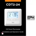
CDT2-24  
24V Room Thermostat  
Installation and Operation Guide  
GeneralDetails
NameEPH Controls CDT2-24 24V Room Thermostat Installation Guide
MakeEPH CONTROLS
LanguageEnglish
FiletypePDF (Download)
File size0.61 MB
Download PDF
1 Star2 Stars3 Stars4 Stars5 Stars (1 votes, average: 5.00 out of 5)
Loading...
EPH CONTROLS eTRV-HW Smart Cylinder Thermostat User Guide
EPH CONTROLS eTRV-HW Smart Hot Water Thermostat Instruction Manual
EPH CONTROLS eTRV Smart Radiator Thermostat Instruction Manual
EPH CONTROLS 20221026 RFRA – RF Room Thermostat Instruction Manual
EPH CONTROLS CDTP2 Hardwired Room Thermostat Instruction Manual
EPH CONTROLS RFCA RF Cylinder Thermostat Instruction Manual
EPH CONTROLS PR092K7 RF Cylinder Thermostat Instruction Manual
EPH CONTROLS COMBIPACK2 Smart Thermostat with Automation and Optimum Start Instructions
EPH CONTROLS RFR RF Room Thermostat Instruction Manual
EPH CONTROLS CMF Room Frost Thermostat Instruction Manual

EPH Controls CDT2-24 24V Room Thermostat Installation Guide
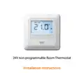
Get the free PDF manual for the EPH Controls CDT2-24 24V Room Thermostat Installation Guide and access setup steps, usage instructions, and troubleshooting tips. 👉 View online or download now to keep your thermostat running smoothly!
EPH Controls CDT2-24 24V Room Thermostat Installation Guide Overview
Summary of Contents

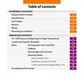
  • Page 1: 24V room thermostat Installation and operation guide
  • Page 2: Installation instructions Factory default settings Specifications LCD display Buttons Wiring Mounting & installation Operating instructions On / off function & adjusting the target temperature Locking the keypad / backlight
  • Page 3: 24V non-programmable room thermostat Installation instructions
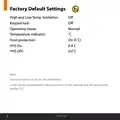
  • Page 4: Factory default settings High and low temperature limitation Keypad lock Operating mode Temperature indicator Frost protection HYS On Normal Frost protection is built into this thermostat. It will only be activated when the thermostat is in OFF position and the temperature reaches 5˚C.
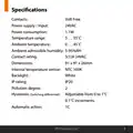
  • Page 5: Specifications Power supply / Input: 24VAC Power consumption: 1.1W Temperature range: 5 … 35˚C Ambient temperature: 0 … 45˚C Ambient admissible humidity: 5-95%RH Contact rating: 5(1)A 24VAC Dimensions: 91 x 91 x 26mm Internal temperature sensor: NTC 100K Backlight: White IP rating: IP20
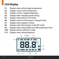
  • Page 6: LCD display provides various indicators for thermostat settings and statuses. It displays when setting the target temperature and shows the current room temperature. The display indicates the current and target temperature, as well as when changing mode settings. It also shows when the thermostat is in TPI mode and when it is calling for heat. The display indicates when the keypad is locked and when the thermostat is in the OFF mode. It shows when setting high and low temperature limits and during calibration mode. Additionally, it displays when setting hysteresis.
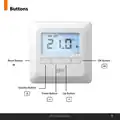
  • Page 7: Reset button. OK button. Standby button. Down button. Up button. EPH Controls Ltd.
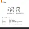
  • Page 8: Wiring Terminal connections 24VAC supply 24VAC live in 24VAC neutral in Normally closed connection Common connection Normally open connection
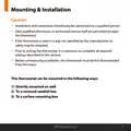
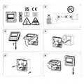
  • Page 9: Mounting & installation Installation and connection should only be carried out by a qualified person. Only qualified electricians or authorised service staff are permitted to open the thermostat. If the thermostat is used in a way not specified by the manufacturer, its safety may be impaired. Prior to setting the thermostat, it is necessary to complete all required settings described in this section. Before commencing installation, the thermostat must be first disconnected from the mains. This thermostat can be mounted in the following ways: directly mounted on wall, to a recessed conduit box, or to a surface mounting box.
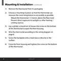
  • Page 10: Mounting & Installation Remove the thermostat from its packaging. Choose a mounting location so that the thermostat can measure the room temperature as accurately as possible. Mount the thermostat 1.5 metres above the floor level. Prevent direct exposure to sunlight or other heating/cooling sources. Use a Philips screwdriver to loosen the screw on the bottom of the thermostat to open the front housing. Wire the thermostat according to the wiring diagram on page 6. Screw the backplate onto a back box or directly to the surface. Close the front housing and tighten the screw on the bottom of the thermostat.
  • Page 11: Page 11
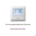
  • Page 12: 24V non-programmable room thermostat Operating instructions
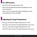
  • Page 13: On/Off function allows you to turn the thermostat on or off. In ON mode, the thermostat displays the current room temperature. In OFF mode, the thermostat displays the current room temperature and the word ‘OFF’. You can adjust the target temperature from 5-35˚C. Press to increase the target temperature. Press to decrease the target temperature. The target temperature is saved after pressing or waiting 5 seconds.
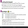
  • Page 14: Locking the keypad To lock the thermostat, press and hold specific buttons for 10 seconds. A lock icon will appear on the screen. The buttons are now disabled. To unlock the thermostat, press and hold the same buttons for 10 seconds. The lock icon will disappear from the screen. The buttons are now enabled. Backlight There are three settings for selection: AUTO, OFF, and ON. The backlight is on for 5 seconds when any button is pressed. The backlight can be adjusted by pressing and holding specific buttons for 10 seconds. Use specific buttons to change the mode between AUTO, ON, and OFF. Press a specific button to confirm selection and return to normal operation.
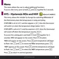
  • Page 15: Menu allows the user to adjust additional functions. To access the menu, press and hold specific buttons for 5 seconds. HYS – Hysteresis HOn and HOF settings can be adjusted. HOn is set at 0.4°C and HOff at 0°C. The thermostat switches on when the temperature drops below the setpoint minus the hysteresis value. The thermostat switches off when the temperature reaches the setpoint plus the hysteresis value. To access the HYS setting, press and hold specific buttons. Use the buttons to select the HOn and HOF temperatures. Press specific buttons to confirm the selected temperatures. Press to return to normal operation.
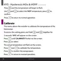
  • Page 16: HYS - Hysteresis HOn & HOFF Press and the temperature will begin to flash. Use and to select the ‘HOF’ temperature, press to confirm. Calibrate This menu allows the installer to calibrate the temperature of the thermostat. To access this setting press and hold and together for 5 seconds. ‘HYS’ will appear on the screen. Press until ‘CALIBRATE’ flashes on the screen. The actual temperature will flash on the screen. Press and to calibrate the temperature.
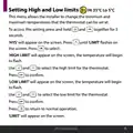
  • Page 17: Setting high and low limits allows the installer to change the minimum and maximum temperatures for the thermostat. The high limit can be set to 35°C and the low limit to 5°C. To access this setting, press and hold two buttons together for 5 seconds. 'HYS' will appear on the screen. Press until 'LIMIT' flashes on the screen and then press to select. 'HIGH LIMIT' will appear on the screen, and the temperature will begin to flash. Use the buttons to select the high limit for the thermostat and press to confirm. 'LOW LIMIT' will appear on the screen, and the temperature will begin to flash. Use the buttons to select the low limit for the thermostat and press to confirm. Press to return to normal operation.
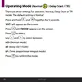
  • Page 18: Operating mode has three settings: Normal, Delay Start, or TPI. The default setting is Normal. To change the setting, press and hold two buttons together for 5 seconds. 'HYS' will appear on the screen. Use the buttons to select until 'MODE' appears on the screen. Select between Normal mode, Delay Start mode, or Time proportional integral mode. Press to confirm the mode.
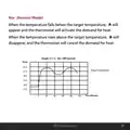
  • Page 19: Nor (Normal Mode) When the temperature falls below the target temperature, the thermostat will activate the demand for heat. When the temperature rises above the target temperature, the thermostat will cancel the demand for heat. On / Off Control Target temperature is set at 21˚C.
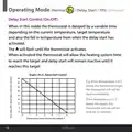
  • Page 20: Operating mode includes normal, delay start, and TPI. Delay start control can be turned on or off. In delay start mode, the thermostat is delayed by a variable time based on current and target temperatures. The indicator will flash until the thermostat activates. Once activated, the thermostat allows time for the heating system to reach the target temperature. Delay start remains inactive until the target temperature is reached. If the temperature is significantly below the target, the thermostat will call for heat immediately. If the temperature is only slightly below the target, the thermostat may delay calling for heat for a period of time. A graph illustrates the relationship between temperature below the thermostat setting and delay start activation. The example shows specific temperature thresholds and corresponding delay times for heat activation.
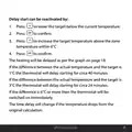
  • Page 21: Delay start can be reactivated by pressing specific buttons to adjust the target temperature. The heating will be delayed as per the graph on page 18. If the difference between the actual temperature and the target is 1°C, the thermostat will delay starting for circa 40 minutes. If the difference is 3°C, the thermostat will delay starting for circa 24 minutes. If the difference is 6°C or more, the thermostat will be switched on immediately. The time delay will change if the temperature drops from the original calculation.
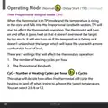
  • Page 22: Operating mode (normal / delay start / TPI) Time proportional integral mode (TPI) In TPI mode, the thermostat adjusts operation to prevent overshooting the target temperature. The thermostat will turn on if the temperature is falling to maintain comfort. Two settings affect the thermostat's operation: the number of heating cycles per hour and the proportional bandwidth. The number of heating cycles per hour determines how often the thermostat cycles heating on and off. You can select from 2, 3, 6, or 12 cycles per hour.
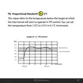
  • Page 23: Proportional bandwidth refers to the temperature below the target at which the thermostat will start to operate in TPI control. You can set this temperature from 1.5°C to 3.0°C in 0.1°C increments. Graph (21.1) illustrates TPI control with target and actual temperatures. The target temperature is set at 22˚C. The thermostat will begin heating when the temperature drops to 21˚C. Heating on and off cycles are represented over time in the graph. The temperature range shown includes values from 17˚C to 22˚C. The time intervals in the graph are marked in minutes. EPH Controls Ltd. is mentioned in the document.
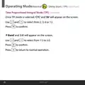
  • Page 24: Operating mode options include normal, delay start, and TPI. In TPI mode, 'CYC' and '06' will appear on the screen. Users can select from options 2, 3, 6, or 12. Press to confirm the selection. 'P Band' and '2.0' will appear on the screen. Users can select a P Band value from 1.5 to 3.0. Press to confirm the P Band selection. Press to return to normal operation.
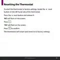
  • Page 25: Resetting the thermostat to factory settings involves locating the reset button on the left-hand side of the thermostat. Press the reset button and release it. 'NO' will flash on the screen. Press to confirm when 'YES' flashes on the screen. The thermostat will restart and revert to its factory settings.
  • Page 26: Page 26
  • Page 27: Page 27
  • Page 28: Page 28