
Home > EPH CONTROLS > EPH CONTROLS RFCA RF Cylinder Thermostat Instruction Manual
EPH CONTROLS RFCA RF Cylinder Thermostat Instruction Manual


Page 1 of 2
Operating Instructions
RFCA - RF Cylinder Thermostat
Contents
1. Factory default settings
3. Mounting
4. Installation
CAUTION!
5. Button / symbol description
6. Resetting the thermostat
7. Boost function
8. Lock function
9. To connect the RFC thermostat to the
RF1 receiver
10. To disconnect the RFC thermostat from
the RF1 receiver
thermostat.
Ensure that this wireless enabled
thermostat is installed 1 metre from any
metalic object, television, radio or wireless
internet transmitter.
Important: Keep this document
Prior to setting the thermostat, it is neccessary to complete all required settings described
in this section.
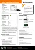
5. Button / symbol description
1. Factory default settings
Temperature indicator:
°C
Wireless symbol
In built frost protection:
5°C
Heating ON symbol
Water temperature
Battery low symbol
Standby button
Power Supply:
2 x AAA Alkaline Battery
Power consumption:
Battery replacement:
Temp. Control Range:
Dimensions:
50 uA
Set point handwheel
Once per year
10...90°C
84 * 84 * 30mm
Temp. sensor:
NTC 10K Ohm @ 25°C - 1.5m probe type
°C
Temp. indication:
3a Mounting of temperature sensor
ON CYLINDER: To ensure accurate control of your cylinder, the temperature
sensor should be mounted on the bottom 1/3 of the cylinder. It is essential that
the sensing element is in direct contact with the cylinder and that there is no
insulation between it and the cylinder. 60°C is the temperature level required in
order to prevent the build up of legionella bacteria. The temperature sensor can
Reset button Code button
6. Resetting the thermostat
Press the
button on the bottom of the thermostat, the front housing
will detach from the baseplate.
ON PIPEWORK: To ensure accurate control, the temperature sensor should be
mounted on the pipework as tightly as possible. It is essential that the sensing
element is in direct contact with the pipework and that there is no insulation
Insert the batteries into the thermostat.
Rotate the hand wheel clockwise until ‘YES’ appears on the screen.
pipework using the provided foil tape.
3b Mounting of thermostat
The thermostat has now been reset and the current temperature will
appear on the screen.
The thermostat should be mounted in a position that will make reading
the display conventient.
2. Surface mounting boxes
3. Directly on walls
4. Installation
Press the button on the bottom of the thermostat.
The front housing will detach from the baseplate.
Insert the batteries (provided) into the thermostat.
8. Lock function
To lock the thermostat, press the hand wheel for 10 seconds.
symbol will appear on the screen.
Mount the unit as described in section 3. Ensure the cable sensor is
connected to terminals Con 3 and Con 4.
To unlock the thermostat, press the hand wheel for 10 seconds.
symbol will disappear from the screen.
EPH Controls Ireland
EPH Controls UK
20221020_RFCA_OpIns_PK


| General | Details |
|---|---|
| Name | EPH CONTROLS RFCA RF Cylinder Thermostat Instruction Manual |
| Make | EPH CONTROLS |
| Language | English |
| Filetype | PDF (Download) |
| File size | 0.2 MB |
 (1 votes, average: 5.00 out of 5)
 Loading...

EPH CONTROLS eTRV-HW Smart Cylinder Thermostat User Guide

EPH CONTROLS eTRV-HW Smart Hot Water Thermostat Instruction Manual

EPH CONTROLS eTRV Smart Radiator Thermostat Instruction Manual

EPH CONTROLS 20221026 RFRA – RF Room Thermostat Instruction Manual

EPH CONTROLS CDTP2 Hardwired Room Thermostat Instruction Manual

EPH Controls CDT2-24 24V Room Thermostat Installation Guide

EPH CONTROLS PR092K7 RF Cylinder Thermostat Instruction Manual

EPH CONTROLS COMBIPACK2 Smart Thermostat with Automation and Optimum Start Instructions

EPH CONTROLS CRT2 Room Thermostat Instruction Manual

EPH CONTROLS CDC2 Cylinder Room Thermostat User Guide

EPH Controls RFCA Manual: Questions and Answers
What do the symbols on the EPH Controls RFCA display mean?
| Symbol | Meaning |
|---|---|
| Wireless symbol | RF connection status |
| Heating ON symbol | Heating is active |
| Battery low symbol | Battery needs replacement |
| Lock symbol | Thermostat controls are locked |
What does the lock symbol mean on EPH Controls?
The lock symbol indicates that the thermostat controls are locked. Press the hand wheel for 10 seconds to unlock and remove the symbol. Instruction Manual, p. 1
More EPH Controls thermostat manuals

NEOMITIS RTE0B Wired Digital Room Thermostat Installation Guide

BEOK CONTROLS BOT306RF WIFI Boiler Thermostat Instruction Manual

Honeywell D1-528 Direct Thermostat Installation Guide

MI-HEAT MST1 Room Thermostat for Underfloor Heating User Manual

Honeywell TL6120 5-2 Electric Heating Programmable Thermostat User Guide

SALUS TS600 Wireless Temperature Sensor Thermostat User Guide

COMPUTHERM E800RF Multizone Wi-Fi Thermostat Instruction Manual

seitron TAD022 Digital Room Thermostat for Heating Cooling System Instruction Manual

HomePilot 13501001 Wireless Room Thermostat User Guide

Homematic IP BMOAONSUT Radiator Thermostat User Manual