Home > EPH CONTROLS > EPH CONTROLS eTRV-HW Smart Hot Water Thermostat Instruction Manual

EPH CONTROLS eTRV-HW Smart Hot Water Thermostat Instruction Manual
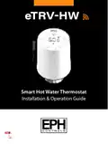
eTRVꢀHW  
Smart Hot Water Thermostat  
Installation & Operation Guide  
GeneralDetails
NameEPH CONTROLS eTRV-HW Smart Hot Water Thermostat Instruction Manual
MakeEPH CONTROLS
LanguageEnglish
FiletypePDF (Download)
File size0.6 MB
Download PDF
1 Star2 Stars3 Stars4 Stars5 Stars (1 votes, average: 5.00 out of 5)
Loading...
EPH CONTROLS eTRV-HW Smart Cylinder Thermostat User Guide
EPH CONTROLS eTRV Smart Radiator Thermostat Instruction Manual
EPH CONTROLS 20221026 RFRA – RF Room Thermostat Instruction Manual
EPH CONTROLS CDTP2 Hardwired Room Thermostat Instruction Manual
EPH Controls CDT2-24 24V Room Thermostat Installation Guide
EPH CONTROLS RFCA RF Cylinder Thermostat Instruction Manual
EPH CONTROLS PR092K7 RF Cylinder Thermostat Instruction Manual
EPH CONTROLS COMBIPACK2 Smart Thermostat with Automation and Optimum Start Instructions
EPH CONTROLS CMF Room Frost Thermostat Instruction Manual
EPH CONTROLS RFRA RF Room Thermostat Installation Guide

EPH CONTROLS eTRV-HW Smart Hot Water Thermostat Instruction Manual
Get the free PDF manual for the EPH CONTROLS eTRV-HW Smart Hot Water Thermostat Instruction Manual and access setup steps, usage instructions, and troubleshooting tips. 👉 View online or download now to keep your thermostat running smoothly!
EPH CONTROLS eTRV-HW Smart Hot Water Thermostat Instruction Manual Overview
Summary of Contents

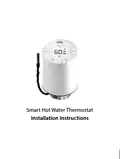
  • Page 1: Smart hot water thermostat Installation & operation guide
  • Page 2: Table of contents Installation instructions Factory default settings Specifications Important notes How your eTRV-HW works Mounting & installation Operating instructions LCD symbol description Button description Replacing the batteries
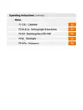
  • Page 3: Operating instructions Calibrate Setting high and low limits Resetting the eTRV-HW Backlight Hysteresis
  • Page 4: Smart hot water thermostat Installation instructions
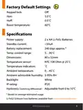
  • Page 5: Factory default settings include keypad lock options and temperature settings. Power supply consists of 2 x AA Li-FeS2 batteries. Standby current is less than 50uA. Temperature control range is from 5 to 90°C. Dimensions of the device are 80 x 52mm. Temperature sensor is an NTC 10K Ohm at 25°C. Ambient temperature range is 0 to 45°C. Ambient admissible humidity is 5-95% RH. Backlight is white. IP rating is IP20.
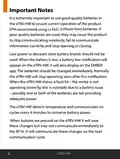
  • Page 6: Important notes It is extremely important to use good quality batteries in the eTRV-HW to ensure correct operation of the product. EPH recommend using Li-FeS2 (Lithium Iron) batteries. Poor quality batteries may cause the product to stop communicating wirelessly and fail to operate correctly. Low power or discount store battery brands should not be used. When the battery is low, a battery low notification will appear on the eTRV-HW and the EMBER app. The batteries should be changed immediately after receiving a low battery notification. The eTRV-HW will stop operating soon after the low battery notification. A fault E4 indicates that the motor is not operating correctly, usually due to a battery issue. The eTRV-HW detects temperature and communicates on cycles every 4 minutes to conserve battery power. Changes made by pressing buttons on the eTRV-HW may not communicate immediately to the RF16 but will be sent on the next communication cycle.
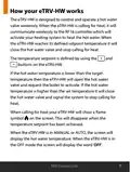
  • Page 7: How your eTRV-HW works The eTRV-HW is designed to control and operate a hot water valve wirelessly. When the eTRV-HW is calling for heat, it will communicate wirelessly to the RF16 controller which will activate your heating system to heat the hot water. When the eTRV-HW reaches its defined setpoint temperature it will close the hot water valve and stop calling for heat. The temperature setpoint is defined by using the buttons on the eTRV-HW. If the hot water temperature is lower than the target temperature then the eTRV-HW will open the hot water valve and request the boiler to activate. If the hot water temperature is higher than the set temperature it will close the hot water valve and signal the system to stop calling for heat. When calling for heat your eTRV-HW will show a flame symbol on the screen. This will disappear when the temperature setpoint has been achieved. When the eTRV-HW is in MANUAL or AUTO, the screen will display the hot water temperature. When the eTRV-HW is in the OFF mode the screen will display the word ‘OFF’.
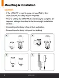
  • Page 8: Mounting & installation If the eTRV-HW is used in a way not specified by the manufacturer, its safety may be impaired. Prior to setting the eTRV-HW, it is necessary to complete all required settings described in the mounting & installation section. Ensure the valve body is free of dust and debris. Ensure the valve body is dry and not leaking.
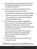
  • Page 9: Press and hold the release mechanism on the side of the eTRV-HW to slide off the cover. Insert the 2 x AA batteries and replace the cover. Pair the eTRV-HW to the RF16. Mark the eTRV zone using the stickers provided. Note the room name on the 16 zone list to help identify the zones in the future. The eTRV-HW can be mounted to a SEMTRVB22C valve with a M30 x 1.5mm thread. Rotate the ring at the base of the eTRV-HW to thread onto the SEMTRVB22C until tight. It’s recommended that the eTRV-HW is opened to make it easier to mount. Position the eTRV-HW on the valve so the screen is orientated correctly. The eTRV-HW is designed for use with SEMTRVB22C Valve.
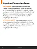
  • Page 10: Mounting of temperature sensor On cylinder: The temperature sensor should be mounted on the bottom 1/3 of the cylinder. It is essential that the sensing element is in direct contact with the cylinder and that there is no insulation between it and the cylinder. The temperature sensor can be fixed to the cylinder using the provided foil tape. In thermal pocket: The temperature sensor should be inserted into the thermal pocket. It is essential that the sensing element is inserted as far as possible. The temperature sensor can be fixed using the provided foil tape.
  • Page 11: Smart hot water thermostat operating instructions.
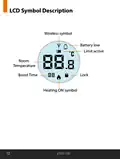
  • Page 12: LCD symbol description includes various indicators. The wireless symbol indicates connectivity status. A battery low symbol alerts the user to low battery levels. Limit active signifies that a limit has been reached. Room refers to the specific area being monitored. Temperature displays the current temperature reading. Boost time indicates a temporary increase in heating. The lock symbol shows that the device is locked. Heating on symbol confirms that the heating system is active.
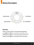
  • Page 13: Button description includes various functions such as the minus button, boost button, plus button, and on/off button. Shortcuts are available for different actions. Holding specific buttons for designated times allows access to features like keypad lock, menu access, and RF connection.
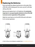
  • Page 14: Replacing the batteries involves pressing and holding the release mechanism on the side of the eTRV-HW while pulling the cover up to slide it off. Remove and replace the 2 x AA batteries, ensuring to use good quality batteries for correct operation. Slide the cover back on to the eTRV-HW to return it to normal operation. Li-FeS2 (Lithium Iron) batteries are available from the specified website.
  • Page 15: Error codes will be displayed if there is a problem with the eTRV-HW. E4 indicates a motor issue and suggests checking the batteries. If E4 persists after using premium batteries, the eTRV-HW needs replacement. A low battery indication will appear on the screen when batteries are low. The low battery icon will also show on the zone in the EMBER App. It is recommended to replace the batteries immediately when the low battery indication appears.
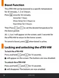
  • Page 16: Boost function allows the eTRV-HW to be set to a specific temperature for a duration of 30 minutes, 1, 2, or 3 hours. Press once for 30 minutes, twice for 1 hour, three times for 2 hours, or four times for 3 hours. After setting the duration, press to set the desired temperature for the boost period. The selected duration will appear on the screen, and the device will return to the home screen after 5 seconds. To cancel a boost while it is active, press the designated button. Locking the eTRV-HW requires pressing and holding two specific buttons for 10 seconds. A lock symbol will appear on the screen indicating the buttons are disabled. Unlocking the eTRV-HW involves pressing and holding the same two buttons for 10 seconds. The lock symbol will disappear, and the buttons will be enabled again.
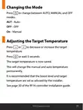
  • Page 17: Changing the mode allows you to switch between AUTO, MANUAL, and OFF modes. Press to change the mode. Adjusting the target temperature can be done by pressing or waiting 5 seconds. The target temperature is saved after adjustment. Changes to the target temperature affect both manual and auto settings permanently. It is recommended to set the boost level and target temperature as advised by the installer. Refer to page 30 of the RF16 controller installation guide for more information.
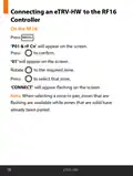
  • Page 18: Connecting an eTRV-HW to the RF16 Controller involves several steps. Press the MENU button to access the settings. ‘P01 & rF Cn’ will appear on the screen. Press to confirm the selection. ‘01’ will appear on the screen after confirmation. Rotate to select the required zone. Press to select that zone. ‘CONNECT’ will appear flashing on the screen. Zones that are flashing are available for pairing, while solid zones have already been paired.
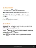
  • Page 19: On the eTRV-HW, press and hold for 5 seconds. ‘nOE’ will appear on the screen followed by ‘ - - ’. The eTRV-HW will display ‘r ‘ followed by the zone number. Press to exit from screen. On the RF16, ‘CONNECTED’ will appear solid on the screen when the eTRV-HW is successfully paired. Rotate to pair the next available zone and repeat the MENU process or press to exit. Press to return to normal operation at any time.
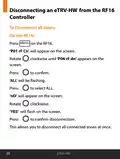
  • Page 20: Disconnecting an eTRV-HW from the RF16 Controller To disconnect all zones: On the RF16, press MENU. ‘P01 rF Cn’ will appear on the screen. Rotate the screen clockwise until ‘P06 rF dn’ appears. Press to confirm. ‘ALL’ will be flashing. Press to select ALL. ‘nO’ will appear on the screen. Rotate clockwise. ‘YES’ will flash on the screen. Press to confirm disconnection. This allows you to disconnect all connected zones at once.
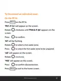
  • Page 21: To disconnect an individual zone on the RF16, press MENU. ‘P01 rF Cn’ will appear on the screen. Rotate the screen clockwise until ‘P06 & rF dn’ appears. Press to confirm. ‘All’ will be flashing. Press to select a hot water zone. ‘nO’ will appear on the screen. Rotate clockwise. ‘YES’ will appear on the screen. Press to confirm disconnection.
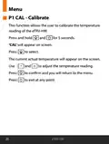
  • Page 22: Menu P1 CAL - Calibrate This function allows the user to calibrate the temperature reading of the eTRV-HW. Press and hold ‘CAL’ will appear on screen. The current actual temperature will appear on the screen. Use and to adjust the temperature reading. Press to confirm and you will return to the menu. Press to exit at any point.
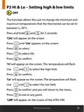
  • Page 23: Hi & Lo – Setting high & low limits This function allows the user to change the minimum and maximum temperatures that the thermostat can be set to between 5...90°C. Press and hold for 5 seconds. ‘CAL’ will appear on the screen. Press until ‘LIn’ appears on the screen. Use to select ON. ‘Hi’ will appear on the screen. The temperature will flash. Use to select the high limit. ‘Lo’ will appear on the screen. The temperature will flash. Use to select the low limit. ‘LIM’ will appear on the screen of the eTRV-HW.
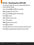
  • Page 24: Resetting the eTRV-HW allows the user to restore factory default settings. To reset, press and hold specific buttons for 5 seconds until 'CAL' appears on the screen. Continue pressing until 'rSt' appears. 'NO' will flash on the screen, and you can adjust to select 'YES'. Press to confirm the reset. The eTRV-HW will reset and go to OFF mode. You can change between Manual, Auto, and OFF modes.
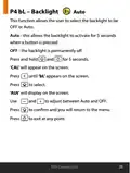
  • Page 25: Backlight settings allow the user to select between OFF or Auto. In Auto mode, the backlight activates for 5 seconds when a button is pressed. In OFF mode, the backlight is permanently off. To access backlight settings, press and hold specific buttons for 5 seconds. ‘CA L’ will appear on the screen during the process. Navigate to ‘b L’ on the screen to select the backlight option. ‘AUt’ will display when Auto is selected. Use designated buttons to adjust between Auto and OFF. Press to confirm the selection and return to the menu. You can exit at any point during the process.
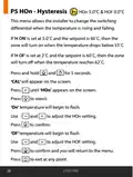
  • Page 26: HOn - Hysteresis This menu allows the installer to change the switching differential when the temperature is rising and falling. If ‘H ON’ is set at 5.0˚C and the setpoint is 60˚C, then the zone will turn on when the temperature drops below 55˚C. If ‘H OF’ is set at 2˚C and the setpoint is 60˚C, then the zone will turn off when the temperature reaches 62˚C. Press and hold for 5 seconds. ‘CAL’ will appear on the screen. Press until ‘HOn’ appears on the screen. ‘On’ temperature will begin to flash. Use to adjust the HOn setting. Press to confirm. ‘OF’ temperature will begin to flash.
  • Page 27: Page 27
  • Page 28: Page 28