Home > Copeland > COPELAND 1F95G-1235GC Humidity Universal Thermostat Instruction Manual

COPELAND 1F95G-1235GC Humidity Universal Thermostat Instruction Manual

Big Blue Humidity Universal Thermostat  
with Humidity/Dehumidity Control and  
Automatic Heat/Cool Changeover Option  
Single Stage, Multi-Stage, Heat Pump  
Installation and Operating Instructions  
Save these instructions for future use!  
FAILURE TO READ AND FOLLOW ALL INSTRUCTIONS  
CAREFULLY BEFORE INSTALLING OR OPERATINGTHIS  
CONTROL COULD CAUSE PERSONAL INJURY AND/OR  
PROPERTY DAMAGE.  
Programming Choices  
7 Day  
5/1/1 Day  
Non-Programmable  
APPLICATIONS  
THERMOSTAT APPLICATION GUIDE  
Maximum  
Stages  
Heat/Cool  
Thermostat  
Configuration Options  
Thermostat  
Applications  
Gas, Oil, Electric, Heat Only,  
Cool Only or Heat/Cool  
Systems, 2 or 3 wire Hydronic  
Zone (Hot Water or Steam)  
Systems, 24 Volt or Millivolt  
Single Stage 1  
No Heat Pump (SS1)  
1/1  
2/2  
Multi Stage 2  
No Heat Pump (MS2)  
Heat Pump 1 Single Stage Compressor  
Single Stage Compressor Heat Pump Systems - up to 2  
3/1  
4/2  
Heat Pump (HP1)  
Stages Aux./Emergency Heat  
Heat Pump 2  
Two Stage or Two  
Compressor Heat Pump  
(HP2)  
Two Stage or Two Compressor  
Heat Pump systems - up to 2  
Stages Aux./Emergency Heat  
SPECIFICATIONS  
Electrical Rating:  
Battery Power. . . . . . . . . . . . . . . . . . . . . . . . . . mV to 30 VAC, NEC Class II, 50/60 Hz or DC  
Input-Hardwire . . . . . . . . . . . . . . . . . . . . . . . . . 20 to 30 VAC  
Terminal Load . . . . . . . . . . . . . . . . . . . . . . . . . . . . . 1.5A per terminal, 2.5A maximum all terminals combined  
Setpoint Range . . . . . . . . . . . . . . . . . . . . . . . . . . . . 45 to 99°F (7 to 37°C)  
Rated Differentials:  
Fast.  
0.6°F  
1.2°F  
1.2°F  
0.6°F  
Slow  
1.5°F  
1.7°F  
1.7°F  
1.7°F  
Heat (Single Stage/Multi-Stage). . . . . . . . . . . .  
Cool (Single Stage/Multi-Stage) . . . . . . . . . . . .  
Heat Pump . . . . . . . . . . . . . . . . . . . . . . . . . . . .  
Emer Heat . . . . . . . . . . . . . . . . . . . . . . . . . . . .  
Operating Ambient. . . . . . . . . . . . . . . . . . . . . . . . . . 32°F to +105°F (0 to +41°C)  
Operating Humidity . . . . . . . . . . . . . . . . . . . . . . . . . 90% non-condensing max.  
Shipping Temperature Range . . . . . . . . . . . . . . . . . -40 to +150°F (-40 to +65°C)  
Dimensions Thermostat. . . . . . . . . . . . . . . . . . . . . . 4-9/16"H x 5-13/16"W x 1-3/16"D  
Humidity Setpoint Range. . . . . . . . . . . . . . . . . . . . . 5 to 50%  
Dehumidification Setpoint Range . . . . . . . . . . . . . . 40 to 95%  
CAUTION  
Topreventelectricalshockand/orequipmentdamage,  
disconnect electric power to system at main fuse or  
circuit breaker box until installation is complete.  
!
ATTENTION: MERCURY NOTICE  
This product does not contain mercury. However, this  
product may replace a product that contains mercury.  
Mercury and products containing mercury must not be  
discarded in household trash. Do not touch any spilled  
mercury. Wearing non-absorbent gloves, clean up any  
spilled mercury and place in a sealed container. For proper  
disposal of a product containing mercury or a sealed  
container of spilled mercury, place it in a suitable shipping  
container. Refer to www.thermostat-recycle.org for  
location to send the product containing mercury.  
Index  
Installation  
Page  
2
3
5
6
10  
12  
15  
Wiring Diagrams  
Thermostat Quick Reference  
Installer Configuration Menu  
Operating Your Thermostat  
Programming  
Troubleshooting  
PART NO. 37-7508C  
Replaces 37-7508B  
1502  
GeneralDetails
NameCOPELAND 1F95G-1235GC Humidity Universal Thermostat Instruction Manual
MakeCopeland
LanguageEnglish
FiletypePDF (Download)
File size0.42 MB
Download PDF
1 Star2 Stars3 Stars4 Stars5 Stars (1 votes, average: 5.00 out of 5)
Loading...
COPELAND ST55 Sensi Smart Thermostat Instruction Manual
COPELAND 1F76U-22WFB Series Sensi Lite Smart Thermostat Installation Guide
COPELAND 026-1739 Programmable Touchscreen Thermostat User Manual
COPELAND P-N 810-1600 Programmable Touchscreen Thermostat User Guide
COPELAND 1F86-0244 Blue 2 Inch Single Stage Thermostat Instruction Manual

COPELAND 1F95G-1235GC Humidity Universal Thermostat Instruction Manual
Get the free PDF manual for the COPELAND 1F95G-1235GC Humidity Universal Thermostat Instruction Manual and access setup steps, usage instructions, and troubleshooting tips. 👉 View online or download now to keep your thermostat running smoothly!

COPELAND 1F95G-1235GC Humidity Universal Thermostat Instruction Manual Overview

Summary of Contents

  • Page 1: Big Blue Humidity Universal Thermostat with humidity/dehumidity control and automatic heat/cool changeover option. Single stage, multi-stage, heat pump installation and operating instructions. Failure to read and follow all instructions carefully before installing or operating this control could cause personal injury and/or property damage. Programming choices include 7 day, 5/1/1 day, and non-programmable options. Thermostat application guide includes configurations for gas, oil, electric, heat only, cool only, and heat/cool systems. Electrical rating: battery power from mV to 30 VAC, NEC Class II, 50/60 Hz or DC. Setpoint range is 45 to 99°F (7 to 37°C). Operating ambient temperature range is 32°F to +105°F (0 to +41°C). This product does not contain mercury, but may replace a product that does. Caution: to prevent electrical shock and/or equipment damage, disconnect electric power to the system at the main fuse or circuit breaker box until installation is complete.
  • Page 2: Installation Thermostat power method Thermostat installation and all components of the control system shall conform to Class II circuits per the NEC code. Battery powered, no 24 Volt system power available. Remove old thermostat and mark wires for terminal identification. Installing new thermostat involves pulling the thermostat body off the base and marking mounting hole locations. Fasten base snugly to wall using mounting holes and two mounting screws. Connect wires to terminal block on base using appropriate wiring schematic. Push excess wire into wall and plug hole with a fire resistant material. For best results, use a premium brand AA alkaline battery. The Power Stealing Switches should be left in the On position for most systems.
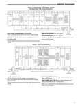
  • Page 3: Wiring diagrams for single stage or multi-stage systems are provided. Single stage systems use a single transformer and include various terminals for configuration. Installer configuration menu allows selection of O or B for changeover function. Fault or system malfunction indicators are included for heat pumps. A 24 volt common connection is optional for system operation. Blower/circulator fan is energized on a call for cool or fan on. Multi-stage systems can be configured for gas, oil, or electric systems. Heat pump connections are specified for both single and multi-stage compressor systems. Refer to equipment manufacturers’ instructions for specific system wiring information. After wiring, consult the installer configuration section for proper thermostat configuration.
  • Page 4: Wiring diagrams provide essential information for system setup. The DHM terminal is used on systems with a compatible dehumidification feature. Humidification terminal energizes on call for heat if humidity setpoint is above room humidity. A relay should be installed to switch the fan speed to a lower speed for dehumidification. The reduction in air flow allows the coil to remove more humidity from the air. The anti-freeze-up control is recommended to prevent the air conditioning coil from freezing. Typical wiring for dehumidifier and humidifier systems is illustrated in the figures. The relay should be rated for blower motor load. Configuration menu item #34 selects humidification. The CAFC breaks the compressor circuit when the suction line drops below 38°F.
  • Page 5: Thermostat quick reference provides essential information for users. Home screen displays room temperature, set temperature/humidity, day of the week, and time of day. Battery level indicator shows the current power level of the batteries. Menu key allows access to different modes such as cleaning, configuration, set time, and set schedule. Displays indicate when the thermostat is calling for heat or cool, and when the batteries should be replaced. Keypad lockout mode limits access to certain functions. Change Filter, Change Pad, and Change UV Lamp reminders appear when maintenance is due. Cool Savings feature indicates energy-saving mode status. Hold mode displays the current temperature setting and duration of the hold. Call for Service alerts users to faults in the heating or cooling systems.
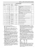
  • Page 6: Installer/configuration menu instructions include pressing the menu touch key and holding the installer config touch key for 5 seconds. Screen reference numbers appear in the top right corner of the display. Shaded items are not available if selected for non-programmable. To default the programming, press the system keys simultaneously. Configuration menu items must match the heat pump system for heat pump systems. Options include selecting between multi-stage, heat pump, or single stage. Settings for gas and electric configurations determine blower control. The system switch configuration varies between non-heat pump and heat pump modes. Energy management recovery and adjustable anticipation settings are available. Temperature limits and keypad lockout options can be configured.
  • Page 7: Installer/configuration menu Configuration menu Selects Dual Fuel feature On or OFF. Selects Dual Fuel setpoint (°F) with outdoor sensor available. Selects Dual Fuel setpoint (°F) with no outdoor sensor. Selects compressor off delay in seconds. Selects Auxiliary Heat cut out temperature. Selects Blower balance point. Selects Humidity Display alternate with time. Selects Auto Humidity reduction. This thermostat is configured for Heat and Cool with Auto changeover default. Energy Management Recovery (EMR) causes the thermostat to start heating or cooling early.
  • Page 8: INSTALLER/CONFIGURATION MENU The principle of this energy saving feature takes advantage of the long air conditioning run times lowering the indoor humidity allowing a slightly higher temperature to feel comfortable. Selecting Compressor Lockout (CL) will cause the thermostat to wait 5 minutes between cooling cycles to help protect the compressor from short cycling. In low lighting conditions, display backlight improves the display contrast. This allows you to adjust the room temperature display by -5°F to +5°F in 1° steps. Changes the display readout to Celsius or Fahrenheit as required. Select Audio Prompting (Beeper) On or Off – Factory default setting is On. This feature will allow the thermostat to calculate Daylight Saving Time automatically. Select Automatic Schedule – This feature allows programming a “Comfort Temperature” into all program periods. Cool Savings™ provides an energy saving temperature offset (from 1-6 degrees) under peak cooling load conditions. Compressor Optimization provides a delay in circulator fan operation after the compressor turns on or off.
  • Page 9: Installer/configuration menu Select remote sensor as indoor or outdoor. Select local sensor disable. Cool temperature limit range adjusts the lowest setpoint temperature for cool. Select dual fuel feature applicable only in heat pump modes. Select dual fuel temperature to determine when to switch to gas heat. Select dual fuel setting influences when second stage comes on. Keypad lockout allows selection of the type of lockout or limited range security. Select compressor delay to set the time delay for compressor shut down. Select auxiliary off to inhibit the auxiliary heating stage based on outdoor temperature. Select fast second stage to force additional heat stages to come on quickly.
  • Page 10: Installer/configuration menu Stage heat when the outdoor temperature is below the selected temperature. Humidity display (Hd) – Selecting HD On enables the display to alternately show the current time and the humidity. Adjustable humidity display – The display will show the ambient humidity and can be changed from -20 and LO to 20 and HI. Auto humidity reduction (HR) – This feature automatically lowers humidity setting when the outside temperature drops. Automatic humidification (AH) – This feature allows for humidification independent of a call for heating. Cycle humidifier (CH) – This feature reduces water usage by up to 50% when a flow-through humidifier is controlled by the thermostat. Change UV lamp – This feature displays a reminder to maintain your UV system after a set time of UV bulb operation. Change humidifier pad – This feature displays a reminder to maintain or clean your humidifier after a set time of operation. Select change filter run time – This feature allows the thermostat to display Change Filter after a set time of blower operation. Programmable dehumidification optimal comfort mode (OC) or optimal dehumidification (Od) – This item can be selected to OC, Od, or OFF.
  • Page 11: Operating your thermostat The second stage cooling should begin to operate and the display should show System On +2. Press SYSTEM key to select HEAT. If the auxiliary heating system has a standing pilot, be sure to light it. To check the dehumidifier when System On appears and the cooling system is running press HUMIDITY button once. Adjust temperature setting to 3° above room temperature. The auxiliary heat system should begin to operate and the display will show System On +2. Press to adjust the humidity 2% or more below the room humidity level setpoint range. DeHum On will appear indicating it is calling for the dehumidification. Emergency Heat (System EM Position) bypasses the Heat Pump to use the heat source wired to terminal W/E, W2 on the thermostat. Pressing FAN until FAN Prog appears activates the Comfort Circulating Fan Option. Press SYSTEM key to select EM. “EM Heat Mode” will flash on the display. Auto Changeover is used in areas where both heating and cooling may be required on the same day. To prevent compressor and/or property damage, if the outdoor temperature is below 50°F, DO NOT operate the cooling system.
  • Page 12: Operating your thermostat Override period can range from 15 minutes to 7 days. Manual operation will bypass the program and allow you to adjust the temperature as you desire. To cancel the temporary setting at any time and return to the program, press Run Schedule. The HOLD key will appear when you adjust the temperature. Press both keys simultaneously to change to the other mode. To copy a program from one day to another, press Menu key to enter installer menu. The display will show “Copy” next to the SYSTEM key and the day of the week that will be copied. The Real Time Clock will adjust automatically for daylight savings time. When programming your thermostat, you may copy the program from one day to another day or group of days using the Copy key.
  • Page 13: Enter the cooling program by pressing the SYSTEM key until the Cool icon appears. Follow the instructions for entering cooling times and temperatures. Auto Schedule Heat is a fast way to program all heating temperatures during the day and lower the temperature at night. Auto Schedule Cool will program all cooling time periods to the same temperature. The thermostat can be programmed for 75° for all cooling time periods. In Heat mode, press Auto Schedule once to set the heating program. The default state of the Fan key is FAN Auto, which can be changed to FAN Prog. The thermostat is programmed with energy-saving settings for all days of the week. You can eliminate program periods in the configuration menu if the building is occupied all day. Keep guidelines in mind when planning your program for energy savings.
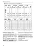
  • Page 14: Programming worksheet for re-programming 5+1+1 and 7 day program. Heating program includes settings for wake up, leave for work, return home, and go to bed. Cooling program also includes settings for wake up, leave for work, return home, and go to bed. Wired remote temperature sensing allows the thermostat to display temperature from either the thermostat or remote sensor. One remote temperature sensor can be installed indoors or outdoors and connected to the thermostat. The thermostat must have a 24 VAC common connection for the remote sensor to operate. The remote sensor can be enabled or disabled in the installer/configuration menu. When enabled, the display alternates between time and remote temperature. The remote sensor can be set as indoor or outdoor. Outdoor temperature range is -40°F to 140°F; indoor temperature range is 32°F to 99°F.
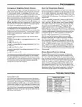
  • Page 15: Programming Averaging or weighting remote sensors The thermostat will weight or average the temperature of the indoor remote sensor with the local sensor in the thermostat for each program period. When the thermostat is configured for Heat Pump mode and the Dual Fuel feature is selected on, the thermostat can monitor the outside temperature using remote sensor F145-1378. The user selectable temperature is called the dual fuel temperature setpoint, dF, and is set in the Installer/Configuration menu. With outdoor remote sensor installed and enabled, the dual fuel temperature setpoint can be set to a temperature of -5° through 50°. A higher temperature or dual fuel setting will provide a smaller stage separation between the heat pump and Aux to give more comfort. In normal operation of the thermostat, the current temperature displayed will be the weighted average of the local sensor and the remote sensor. Blower balance point for heating allows you to select an outdoor temperature to slow the fan speed so the air from the duct feels warmer. Comfort Alert Codes The Comfort Alert diagnostics product monitors the air conditioning outdoor systems with single phase Copeland Scroll compressors. Abnormal system and electrical conditions are indicated by flashing ALERT codes on the yellow LED on the Comfort Alert module.
  • Page 16: Troubleshooting Reset operation: If a voltage spike or static discharge causes erratic thermostat operation, reset the thermostat by removing it from the wall plate and taking out the batteries for 2 minutes. Common problems: No heat, no cool, or no fan can be caused by a blown fuse, tripped circuit breaker, or loose connections. No heat: Possible causes include an unlit pilot light, furnace lock-out condition, or the need for service or thermostat replacement. Diagnostic for no heat: Set the system switch to heat and raise the setpoint above room temperature. A soft click indicates proper operation. No cool: Similar diagnostic steps as no heat, but set the thermostat to cool and lower the setpoint below room temperature. Constant running: Possible wiring shorts or incorrect fan switch settings may cause the heat, cool, or fan to run constantly. Thermostat setting disagreement: The thermostat thermometer setting can be adjusted by +/- 4 degrees. Cycle rate issues: The location of the thermostat or the size of the heating system may influence the cycle rate. Adjust settings in the configuration menu if necessary. Forgot keypad lockout code: Press and hold the menu key for 20 seconds to unlock the thermostat. Blank display: A voltage spike or static discharge may require a reset operation.