
COPELAND 1F95G-1235GC Humidity Universal Thermostat Instruction Manual








INSTALLER/CONFIGURATION MENU
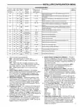
to the left of your setpoint temperature when using this
feature. The "temperature limit" icon will flash if an
attempt is made to adjust the temperature beyond the
range selected.
plays the sensor temperature in the clock digits. OFF (de-
fault) indicates no remote sensor connected or enabled.
31. Select Remote Sensor as Indoor or Outdoor – If 30
is enabled, select the remote to be Remote In (Indoor,
F145-1328) or Outdoor Remote (Outdoor, F145-1378).
Default is Remote In.
32. Select Local Sensor Disable – If 31 is selected Remote
In, the thermostat Local Sensor can be disabled so the
displayed temperature will be from the Remote Sensor.
Default is On LS. To disable the Local Sensor, change
selection to OFF LS.
25. Cool Temperature Limit Range – This feature adjusts
the lowest setpoint temperature for cool. The default
setting is 45°F. It can be changed to a setting between
46°F and 82°F. The "temperature limit" icon will be dis-
played to the left of your setpoint temperature when using
this feature. The "temperature limit" icon will flash if an
attempt is made to adjust the temperature beyond the
range selected.
33. Select Dual Fuel Feature (dF) – This feature is appli-
cable only in heat pump modes (HP1, HP2). Enables (On)
or disables (Off) dual fuel feature of thermostat.
34. Select Dual Fuel Temperature – With dF selected On
and outdoor remote sensor available, select the outdoor
temperature the thermostat will use to determine when to
switch to gas heat and shut down the compressor. When
the outdoor temperature falls below the selected tempera-
ture the gas heat will begin. Default is 35°, but can be set
in the range of -20 to 50°. A lower setting will delay the
start of gas heat allowing cooler temperature in the home.
35. Select Dual Fuel Setting – With DF selected On and no
outdoor sensor, select the dF setting from 01-09. Fac-
tory default is 05. The dF setting influences when second
stage comes on. The factory default creates a separation
of approximately 1°F between stages. Increasing the set-
ting decreases the separation between stages. Decreas-
ing the value increases stage separation. This adjust-
ment allows a small change in the operation of your heat
pump system versus your auxiliary system relative to the
thermostat adjustment. The higher the number the sooner
the auxiliary stage energizes for better comfort. The lower
the number the longer period of time before auxiliary is
energized for more economy.
26 & 27. Keypad Lockout – This step allows you to select
the type of lockout or limited range security required. If no
lockout or limited range security is required, press
advance the menu.
to
Three security settings are available in this menu item.
Use the or keys to select the lockout desired.
Lockout selections are:
"Keypad Lockout and L" = Total Lockout. Total Lockout
locks all keys.
"Keypad Lockout and P" = Partial Lockout. Partial Lock-
out allows only the
set temperature limits.
or
keys to operate within your
"Temperature Limit/Keypad Lockout" prevents chang-
ing the temperature limits in the Configuration Menu.
After the type of lockout is selected, press
.
Keypad Lockout Combination Number Selection
Display will read "000" "Keypad Lockout".
Skip this step and continue through the remainder of the
configuration menu if you require an Air Filter Change
out indicator or Humidifier Pad Change out indicator by
pressing the
key to advance.
Return to this point when you are ready to start your
selected lock-out and continue by:
Pressing
or
keys to select your keypad lockout
Note: This setting is not minutes or degrees. It is numeric set-
ting that will influence the internal thermostat calculation
for staging.
36. Select Compressor Delay (Cd) – After the auxiliary heat
is turned on, the compressor(s) shut down is delayed for
the time selected (in seconds). This delay is factory set to
60, but can be set in the range of 0 to 99.
37. Select Auxiliary Off (AO) – Applicable with HP1 or HP2
selected with outdoor sensor. Select the temperature
that will inhibit the auxiliary heating stage. As long as the
outdoor temperature is above the selected temperature,
the auxiliary heat will not turn on. The default setting is
80°(disabled), but can be set in the range of -20° to 79°.
Thermostat will not allow a setting at or below the (dF)
dual fuel setting.
combination number. Note: "000" is not a valid
combination choice.
Record the number you select for future use.
Press
to exit the menu. The security feature you select
will start in 10 seconds. The system key will remain active
for 10 seconds to allow setting Heat, Off, Cool or Auto.
To unlock the keypad, press Menu, then press Installer
Config. Display will show "000" and keypad lock. Enter
the code used to lock the keypad and press
28 & 29. Select Fast Second Stage, ON or OFF – Not
.
available if configured for SS1. Selecting FA ON forces
additional heat stages to come on quickly when
used to raise the temperature a few degrees above the
room. Select this setting if you want the heat to increase
quickly when you manually raise the temperature.
is
If indoor temperature drops below 45° because of a pos-
sible heat pump malfunction, the thermostat will turn off
the pump and switch to Auxiliary heat. "Call for Service"
will display on screen.
Selecting FA OFF allows the thermostat to calculate an
optimal time to bring on additional stages of heat. When
the
is used to raise the setting above the room tem-
perature additional heat stages may come on very quickly
or very slowly (up to 30 minutes later) depending on
recent system performance. Select this setting if you do
not require the additional heat stages to come on quickly
when you manually raise the setting and want to allow the
thermostat to stage based on recent system performance.
The Fast Cool feature operates the cooling stages in the
same manner as Fast Heat, On or Off when the tempera-
ture is lowered below the room setting.
There are two ways the thermostat will return to normal
heat pump operation:
• Pressanykeytoretrythepumpanderasethe"callfor
service icon.
• WhensetpointisachievedonAuxiliary,systemwill
return to heat pump operation on next call for heat.
38. Select Programmable Blower Balance Point (bP) –
Applicable with HP1 or HP2 selected, dF On with outdoor
sensor. Requires DHM connection from thermostat to
heat pump system. This feature de-energizes the DHM
terminal to operate the blower at a slower speed for first
30. Select Remote Temperature Sensor Enabled – ON
enables a remote sensor connected to thermostat and dis-
9

| General | Details |
|---|---|
| Name | COPELAND 1F95G-1235GC Humidity Universal Thermostat Instruction Manual |
| Make | Copeland |
| Language | English |
| Filetype | PDF (Download) |
| File size | 0.42 MB |
 (1 votes, average: 5.00 out of 5)
 Loading...

COPELAND ST55 Sensi Smart Thermostat Instruction Manual

COPELAND 1F76U-22WFB Series Sensi Lite Smart Thermostat Installation Guide

COPELAND 026-1739 Programmable Touchscreen Thermostat User Manual

COPELAND P-N 810-1600 Programmable Touchscreen Thermostat User Guide

COPELAND 1F86-0244 Blue 2 Inch Single Stage Thermostat Instruction Manual


PRO1 T771 Programmable Electronic Thermostat Instructions

resideo P200 Series Focus PRO Thermostat User Guide

Danfoss RT 115 Thermostat Installation Guide

STELPRO ST302P Programmable Electronic Thermostat Owner’s Manual

Danfoss ECtemp Smart Intelligent Electronic Timer Thermostat Installation Guide

PRO1 R250W Wireless System Thermostat Owner’s Manual

SmartLife ZBHTR20WT Zigbee Radiator Thermostat Installation Guide

FRICO TAP16R Electronic Thermostat User Guide

Network Thermostat X5-WIFI Smart Touchscreen Thermostat Instruction Manual

hansgrohe 24240XXX Shower Column Including Thermostat Instruction Manual