
Home > WHITE RODGERS > WHITE RODGERS 1F80-51 Programmable Electronic Digital Thermostat Instruction Manual
WHITE RODGERS 1F80-51 Programmable Electronic Digital Thermostat Instruction Manual
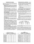
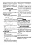


INSTALLATION
REMOVE OLD THERMOSTAT
1. Shut off electricity at the main fuse box until installation is
complete. Ensure that electrical power is disconnected.
2. Remove the front cover of the old thermostat. With wires
still attached, remove wall plate from the wall. If the old
thermostathasawallmountingplate,removethethermostat
and the wall mounting plate as an assembly.
3. Identifyeachwireattachedtotheoldthermostatusingthe
labels enclosed with the new thermostat.
ELECTRIC
GAS
4. Disconnect the wires from old thermostat one at a time. DO
NOT LET WIRES FALL BACK INTO THE WALL.
5. Install new thermostat using the following procedures.
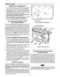
Electric/Gas switch
ELECTRIC HEAT OR SINGLE-STAGE
HEAT PUMP SYSTEMS
Figure 1. Back of thermostat base
Read entire paragraph before setting electric heat switch. If you
areunsureofyourapplication,contactaqualifiedserviceperson.
Alkaline batteries (3 "AA"–
install "+" ends to the left)
If you have a single-stage heat pump system, OR your system
uses central electric heat, where the blower is energized by a
separate circuit through the fan relay (meaning that the fan
turns on immediately on call for heat), then the switch on the
back of the thermostat base must be moved to the “ELECTRIC”
position (see fig 1). If the thermostat is energizing electric heat
sequencers, the switch MUST remain in the “GAS” position.
Screw anchors
If you must move the switch to the “ELECTRIC” position (to the
left), use a small screwdriver or pencil.
RH
W
RC
B
G
ATTACH THERMOSTAT BASE TO WALL
Y
O
1. Remove the packing material from the thermostat. Gently
pull the cover straight off the base. Forcing or prying on the
thermostatwillcausedamagetotheunit. Ifnecessary, move
the electric heat switch (see ELECTRIC HEAT SYSTEMS,
above).
Mounting
holes
2. Connect wires beneath terminal screws on base using
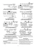
appropriate wiring schematic (see figs. 3 through 10).
Figure 2. Thermostat base
3. Place base over hole in wall and mark mounting hole
locations on wall using base as a template.
4. Move base out of the way. Drill mounting holes.
5. Fasten base loosely to wall, as shown in fig. 2, using two
mounting screws. Place a level against bottom of base,
adjust until level, and then tighten screws. (Leveling is for
appearance only and will not affect thermostat operation.) If
you are using existing mounting holes, or if holes drilled are
too large and do not allow you to tighten base snugly, use
plastic screw anchors to secure subbase.
HYDRONIC (HOT WATER OR STEAM)
HEATING SYSTEMS
This thermostat is set to operate properly if you have a forced-
air heating system. If you have a hydronic heating system (a
system that heats with hot water or steam), you must set the
thermostat to operate properly with your system. While in the
HEAT mode, change the setting by pressing and holding SET
TIMEandVIEWPRGMbuttonsatthesametimeuntilthecorrect
setting is displayed (A for forced air; H for hydronic systems). If
there is a loss of battery power, or when you change batteries,
you must repeat this operation once battery power is restored.
6. Push excess wire into wall and plug hole with a fire-resistant
material(suchasfiberglassinsulation)topreventdraftsfrom
affecting thermostat operation.
BATTERY LOCATION
This thermostat requires 3 “AA” alkaline batteries to operate.
Batteries are installed in the thermostat at the factory with a
battery tag to prevent power drainage. You must remove the
batterytagtoengagethebatteriesandprovidepowertothe
thermostat.
NOTE
If you do not press both buttons at the same time, A or H will not
bedisplayed. Ifthishappens, pressRUNPRGM, thenpressand
hold SET TIME and VIEW PRGM at the same time.
If the word BATTERY is displayed, the batteries are low and
shouldbereplacedwithfresh“AA”Energizer® alkalinebatteries.
To replace the batteries, install the batteries along the top of the
base (see fig. 2). The batteries must be installed with the
positive (+) ends to the left.
2

| General | Details |
|---|---|
| Name | WHITE RODGERS 1F80-51 Programmable Electronic Digital Thermostat Instruction Manual |
| Make | WHITE RODGERS |
| Language | English |
| Filetype | PDF (Download) |
| File size | 0.12 MB |
 (1 votes, average: 5.00 out of 5)
 Loading...

White-Rodgers 1E78 Non Programmable Heat Only Thermostat User Manual

White-Rodgers 1F97-1277 Big Blue Single Stage Thermostat User Manual

White-Rodgers 1F56N-444 Thermostat User Manual

White-Rodgers 1F83-277 Heating & Air Conditioning Auto Changeover Heat Pump Thermostat User Manual

White-Rodgers M30 Thermostat Instruction Manual

WHITE-RODGERS 1F51N-619 Low Voltage Evaporative Cooler Thermostat Instruction Manual

White Rodgers 1F78-151 Non Programmable Thermostat Instructions

WHITE-RODGERS 1F86-0471 Blue Single 1 1 Stage Thermostat Instruction Manual

WHITE-RODGERS 1F90-71 5-Day 2-Day Electronic Digital Thermostat Instruction Manual

WHITE-RODGERS 1F95-1277 Universal Thermostat Owner’s Manual


Honeywell Home RLV3150 Electric Thermostat User Guide

Roth Minishunt Plus Wireless Room Thermostat Installation Guide

eve thermo 22088 Eve Radiator Thermostat User Manual

AuVerte C501 Thermostat Installation Guide

network thermostat X-Series Ethernet Thermostat Instruction Manual

Google Cloud 2024 Nest Learning Thermostat Instructions

hyco PT01 Programmable Thermostat Instruction Manual

BEOK TDS72 Digital Screen Thermostat Instruction Manual

Honeywell T6 Pro Programmable Thermostat User Manual

RATE R8 Weekly Programmable Handwheel Thermostat Instruction Manual