Home > nVent RAYCHEM > nVent RAYCHEM RAYSTAT-EX-02 Mechanical Thermostat Installation Guide

nVent RAYCHEM RAYSTAT-EX-02 Mechanical Thermostat Installation Guide

RAYSTAT-EX-02  
Installation instructions  
Montageanleitung  
Instructions d’installation  
Instruções de instalação  
Инструкция по монтажу  
GeneralDetails
NamenVent RAYCHEM RAYSTAT-EX-02 Mechanical Thermostat Installation Guide
MakenVent RAYCHEM
LanguageEnglish
FiletypePDF (Download)
File size0.31 MB
Download PDF
1 Star2 Stars3 Stars4 Stars5 Stars (1 votes, average: 5.00 out of 5)
Loading...
nVent RAYCHEM ETS-05 Electronic Thermostat Instruction Manual
nVent RAYCHEM Elexant 3500i Electronic Thermostat Installation Guide
nVent RAYCHEM RayStat-M2 Thermostat Instruction Manual
nVent RAYCHEM Green Leaf Programmable Thermostat Instruction Manual
nVent RAYCHEM AT-TS-13 Surface Sensing Thermostat Instruction Manual
nVent RAYCHEM SENZ Wifi Programmable Floor Heating Thermostat User Guide
nVent RAYCHEM GM-TA Thermostat Instruction Manual

nVent RAYCHEM RAYSTAT-EX-02 Mechanical Thermostat Installation Guide
Get the free PDF manual for the nVent RAYCHEM RAYSTAT-EX-02 Mechanical Thermostat Installation Guide and access setup steps, usage instructions, and troubleshooting tips. 👉 View online or download now to keep your thermostat running smoothly!

nVent RAYCHEM RAYSTAT-EX-02 Mechanical Thermostat Installation Guide Overview

Summary of Contents

  • Page 1: Installation instructions
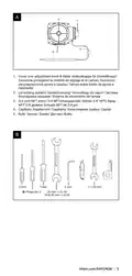
  • Page 2: Cover over adjustment knob & dial. Lid locking system. 3/4 inch NPT entry. Capillary. Bulb.
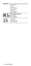
  • Page 3: RAYSTA T-EX-02 II 2 G D Ex db IIC T 6 Gb Ex tb IIIC T 80°C Db IP 66 –40˚C ≤ Ta ≤ +60˚C Ex d IIC T 6 Gb X Ex tb IIIC T 80°C Db X Ta –40°C…+60°C IP 65
  • Page 4: WARNING: Do not open while energized. Only use copper conductors suitable for 90 °C. Special conditions for safe use apply according to IEC/EN 60079-1 regarding thread maintenance. The flamepaths are specified with maximum gaps smaller than those shown in the standard and shall not be enlarged. This thermostat is suitable for installation where the circuit rating is less than 22 A switching current at 480 V. To complete the heating cable system, other components must be selected from the nVent literature. Follow instructions carefully. Our products satisfy the requirements of the relevant European Directives. For cable connection in hazardous areas, verify that the proper type gland is used. In Zone 1 or Zone 2, gas group IIC, use flameproof cable entry devices incorporating compound filled seals.
  • Page 5: Attention: ne jamais ouvrir sous tension. Utiliser uniquement des conducteurs en cuivre supportant 90 °C. Conditions particulières d’utilisation selon la norme IEC / EN 60079-1. Les passages de flamme doivent respecter des interstices maximums inférieurs à ceux indiqués dans la norme. Le fabricant doit être consulté pour connaître les valeurs requises pour la maintenance. Ce thermostat convient aux applications avec des caractéristiques nominales du circuit < 22 A et 480 V. Pour compléter le système de ruban chauffant, sélectionner d'autres composants dans le Guide de sélection des composants. Les produits nVent sont conformes aux exigences des directives européennes. Vérifiez que le bon type de presse-étoupe est utilisé lors du raccordement d’un câble dans un emplacement dangereux. Utilisez des dispositifs d’entrée de câbles antidéflagrants pour les zones 1 ou 2, groupe de gaz IIC.
  • Page 6: Для Зона 1 или Зона 2, группа газа IIC необходимо применять огнестойкие кабельные входы с уплотнениями с заливкой компаундом вокруг отдельных сердечников или другое уплотнительное устройство с соответствующей сертификацией. Во всех других случаях используйте для бронированного кабеля GL-33, а для небронированного кабеля питания – GL-34. Utilizar apenas condutores de cobre indicados para 90 °C. De acordo com a norma IEC/EN 60079-1 relativo à manutenção do rosqueamento da tampa, aplica-se o seguinte: os caminhos das chamas são especificados com intervalos máximos menores do que aqueles indicados na norma e não devem ser aumentados. Este termostato é adequado para instalação onde se aplica o seguinte: Especificação do circuito < 22 A corrente comutada 480 V. Para completar o sistema da unidade de elemento aquecedor, devem ser selecionados outros componentes na literatura da nVent. Siga cuidadosamente as instruções. Declaração de conformidade: Nossos produtos satisfazem os requisitos das Diretivas Europeias relevantes. Para a conexão do cabo na área de perigo, verifique se está a ser utilizado o prensa cabo adequado. Zona 1 ou Zona 2, Grupo de gás IIC: utilize dispositivos de entrada para cabo à prova de fogo que integrem vedações com composto em volta de cada núcleo ou outro dispositivo de vedação certificado adequado.
  • Page 7: Enclosure installation Alternative mounting arrangements are shown. For optimised temperature control, locate enclosure remote from bulb. Locate enclosure to avoid exposure to mechanical damage. Ensure enclosure entries are not directly exposed to water. Different mounting options are illustrated. For better temperature regulation, mount the enclosure away from the sensor. Position the enclosure to protect against potential mechanical damage. Check that the enclosure entries are not directly exposed to water. Ensure optimal alignment of the enclosure.
  • Page 8: Maintenance Maintain thermostat during normal plant maintenance. Check: Mounting is firm. Exposed capillary is not damaged. Gland seal is in place. Gland body and nuts are tightened firmly. Internal and external terminals are tight. Thermostat operation correct. Thermostat set to suit application. Dial cover closed firmly. Lid closed firmly.
  • Page 9: Bulb and capillary installation Location of bulb As indicated in the system design documentation Away from heat sinks such as valves, flanges, supports or pumps At the top of the pipe for thermally sensitive pipe contents On lower quadrant of pipe 90° from single heating cable On lower quadrant of pipe centrally between heating cables if two or more heating cables. For optimal controller function, install sensor as follows Follow the indications provided in the system design documentation Not on parts with increased heat losses such as valves, flanges, supports or pumps.
  • Page 10: Dimensions in mm Bulb and capillary installation Attachment of bulb Fix bulb firmly on pipe surface with heating cable fixing tape in three places. Fix bulb parallel to pipe. Route capillary to avoid damage in use. WARNING: Do not bend bulb, keep it straight at all times. Sensor must be securely mounted and fixed with tape in three places. Fix bulb firmly on the surface of the tube with fixing tape. Ensure the capillary is oriented to avoid damage during operation.
  • Page 11: Heating cable conductor Heating cable braid Cable connections Supply cable gland WARNING: Cable glands supplied by others must meet the requirements for the hazardous area and cable construction applicable. Failure to remove any links between live terminals in the junction box will result in loss of control. Junction box Connection kit NOTE: Live link must be removed by installer nVent RAYCHEM must comply with the requirements for the hazardous area and cables used.
  • Page 12: Cable connections continued Ensure lid retaining grub screw is loose but is retained in plate. Remove lid using spanner if necessary. Install cable through gland, fix gland in place firmly and terminate cable to required standards. Connect cable as shown. Ensure lid retaining grub screw remains clear of lid. Close lid by hand. Tighten lid retaining grub screw. Where required connect external earth terminal provided. Check: Gland seal (grommet) is in place. Gland body and nuts are tightened firmly. WARNING: Ensure lid retaining grub screw is tightened fully to meet hazardous area approval requirements.
  • Page 13: Установочный винт, который крепит крышку, должен не затрагивать крышку. Закройте крышку вручную. Затяните установочный винт, который крепит крышку. Установочный винт, который крепит крышку, должен быть полностью затянут, чтобы соответствовать требованиям монтажа во взрывоопасной зоне. Проверьте: на месте ли уплотнение кабельного ввода. Проверьте прочность затяжки гаек и корпуса сальника кабельного ввода. Если необходимо, подсоедините внешнюю клемму заземления, которая входит в комплект поставки. Certifique-se de que o parafuso de retenção sem cabeça da tampa permaneça afastado da tampa. As conexões do cabo são contínuas. Remova a tampa usando uma chave de porca, se necessário.
  • Page 14: Complete installation Ensure the pipe and bulb are thermally insulated and clad to the design specification after installation of thermostat. Seal cladding with sealant at entry of capillary (A). When thermostat installation is complete test as described in the Installation & Maintenance manual. Retain this instruction for future use e.g. setting, testing, maintenance. Sicherstellen, daß Rohrleitung und Sensor nach der Reglermontage entsprechend der Auslegung wärmegedämmt und verkleidet werden. Verkleidung an Kapillareinführung abdichten (A). Funktionstest gemäß Montage- und Betriebsanleitung durchführen. Certifique-se de que o tubo e o bulbo sejam isolados termicamente e revestidos de acordo com a especificação do projeto após a instalação do termostato. Quand le montage du thermostat est terminé, procéder au test indiqué à la rubrique “Test et Mise en Service”.
  • Page 15: Setting Loosen fixing bolts and remove cover from dial. Adjust knob to required setting. Replace cover firmly by tightening fixing bolts.
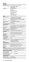
  • Page 16: Thermostat Area of use: Hazardous area: Zone 1, Zone 2 (Gas), Zone 21, Zone 22 (Dust) Approval certification: LCIE 08 ATEX 6095 X Ex db IIC T6 Gb Ex tb IIIC T80°C Db IP66 Enclosure: Body and lid made of lacquer coated cast aluminium with stainless steel fittings Protection: IP 65 if installed with nVent RAYCHEM cable glands Temperature sensing type: Fluid filled bulb and capillary Dimensions: Capillary 3 m long, bulb 197 mm x 8 mm Switching type: Single pole change over volt free contacts (SPDT) Setting range: -4°C to +163°C Ordering details: Part description RAYSTAT-EX-02, PN (Weight) 404385-000 (1770 g)
  • Page 17: Anwendung Bereichsklassifizierung Ex-Bereich: Zone 1 und Zone 2 (Gas), Zone 21, Zone 22 (Staub) Zulassungen Gehäuse und -Deckel Lackbeschichteter Aluminiumguss mit Deckelinnendichtung aus Nitrilgummi. Schutzart Einsatztemperaturbereich –40°C bis +60°C Temperatursensor Flüssigkeitsgefüllter Sensor- und –gefülltes Kapillarrohr Einsatztemperaturbereich –50°C bis +215°C Einpoliger potenzialfreier Wechsler (SPDT) Bestellbezeichnung RAYSTAT-EX-02
  • Page 18: Thermostat Zone d’utilisation Zones explosibles, Zone 1 ou Zone 2 (Gaz) ou Zone 21 ou Zone 22 (Poussières) Zone ordinaire Agréments Protection IP 65 min. avec les presse-étoupe nVent RAYCHEM GL-33 ou GL-34 Température de service – 40°C à +60°C Sonde de température type : Sonde à bulbe et capillaire Interrupteur type : Inverseur unipolaire, contacts hors potentiel Précision ± 4,5°C à 50°C (fermeture du contact)
  • Page 19: Presse-étoupe du câble Область применения: взрывоопасные зоны, зона 1, зона 2 (газ), зона 21, зона 22 (пыль). Сертификация: одобрения LCIE 08 ATEX 6095 X. Корпус и крышка: литой алюминий с лакокрасочным покрытием. Защита: IP 65 если устанавливается с кабельными вводами GL-33 или GL-34. Рабочие условия: температура от –40°C до +60°C окружающей среды. Тип измерения температуры: жидкостной датчик и капиллярная трубка. Материал: нержавеющая сталь (тип 55316). Переключение: однополюсные переключающие контакты без напряжения (SPDT). Номинал: 22 A при 480 В перемен. тока, переключение 100 000 циклов. Точность (включения): ±4,5°C при температуре окружающей среды 21°C и температуре датчика 50°C.
  • Page 20: Соединительные клеммы Питание Внутреннее заземление Внешнее заземление Способ крепления Опорный кронштейн nVent RAYCHEM Комплектующие Информация для заказа Área de uso Certificação de aprovação
  • Page 21: Temperatura de exposição – 50°C a +215°C Raio mínimo de curvatura bulbo não dobrado, 15 mm para capilar Comutação tipo: contatos com borne simples de comutação sem tensão (SPDT) Especificação ajuste 22 A a 480 VCA, comutação (100.000 ciclos) Intervalo – 4°C a +163°C ± 1,7 K Repetibilidade diferencial 5 K Precisão (chave ligada) ± 4,5°C a 21°C ambiente e 50°C de temperatura do sensor Método botão e indicador externos Terminais de conexão alimentação terra interno terra externo Método de montagem suporte nVent RAYCHEM SB-100, SB-101, SB-110, SB-111 ou montagem superficial com 4 furos de fixação (M6) em centros de 101,5 x 101,5 mm
  • Page 22: Page 22
  • Page 23: België / Belgique Norge Österreich Bulgaria Polska Česká Republika Denmark Republic of Kazakhstan Deutschland Россия España Serbia and Montenegro France Schweiz / Suisse Hrvatska Suomi Italia Sverige Türkiye Lietuva/Latvija/Eesti United Kingdom Magyarország Nederland ©2022 nVent. All nVent marks and logos are owned or licensed by nVent Services GmbH or its affiliates. All other trademarks are the property of their respective owners. nVent reserves the right to change specifications without notice. RAYCHEM-IM-INSTALL025-RaystatEX02-ML-2204 PCN 865201-000