
namron Touch Z Wave 16A Thermostat Instruction Manual


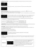




S afety & Warnings
ꢀ DO NOT install with power applied to device.
ꢀ DO NOT expose the device to moisture.
09.ZV09SAPSB.04739
NAMRON Z-WAVE RELÉ 16A
Quick Start
Important: Read All Instructions Prior to Installation
Function introduction
How to install:
ꢀ Step 1: power on the Z-Wave in-wall switch.
ꢀ Step 2: activate inclusion mode on your Z-Wave controller.
ꢀ Step 3: activate inclusion mode of the switch by triple press the action button on the switch. The switch will be
included to Z-Wave network.
Switch input
Product Des cription
LED indicator, indicates when
The in-wall switch is a Z-Wave device that is used to switch ON/OFF the connected light or electrical
appliances and can be controlled by other Z-Wave devices. The In-wall switch can be included and operated in
any Z-Wave network with other Z-Wave certified devices from other manufacturers and/or other applications.
All non-battery operated nodes within the network will act as repeaters regardless of vendor to increase
reliability of the network.
program the switch (inclusion,
exclusion, factory reset)
Action button
This device supports the SmartStart inclusion. SmartStart enabled products can be added into a Z-Wave
network by scanning the Z-Wave QR Code present on the product with a controller providing SmartStart
inclusion. No further action is required and the SmartStart product will be added automatically within a period
after the QR code being scanned or reset power of the device. Please find the QR code on the device casing.
1 CH load output
AC 100-240V power input
The encryption mode that the switch supports is S2 Unauthenticated. When the switch is being included into a
Z-Wave network, you can use your primary controller/gateway to enable encryption mode or disable
encryption. (The primary controller/gateway shall support encryption mode configuration). The switch supports
OTA and can update firmware wirelessly. In addition, the switch is equipped with Power Metering and over
current protection.
Product Data
Z-Wave Frequency
Input Voltage
868.42 MHZ (EU)
AC100-240V
AC100-240V
16A max.
Operation
Output Voltage
Output Current
Operating temperature
Relative humidity
Dimensions
Installation Guide
Please read carefully the enclosed user manual before installation of the in-wall switch, in order to ensure an
error-free functioning.
0 to 40°C
8% to 80%
ATTENTION: Prior to the assembly of the product, the voltage network has to be switched OFF and ensured
against re-switching.
45.5x45x20.3mm
Inclusion (adding to a Z-Wave network)
1. Set primary controller/gateway into inclusion mode (Please refer to your primary controllers manual on how
to turn your controller into inclusion).
Compatible Load T ypes
Load Symbol
Load Type
Maximum Load
Remarks
2. Power on the in-wall switch and set it into inclusion mode. There are two methods to set the in-wall switch
into inclusion mode:
1)Triple press the action button on the switch, LED indicator will flash rapidly, it will set the switch into inclusion
mode for 30 seconds, if there is no reply from the gateway, the device will quit inclusion mode after 30 seconds.
2)When the value of parameter 5 is configured as 1, triple press the external switch rapidly within 1.5 seconds,
LED indicator will flash rapidly, it will set the switch into inclusion mode for 30 seconds, if there is no reply from
the gateway, the device will quit inclusion mode after 30 seconds.
Due to variety of LED lamp
designs, maximum number
of LED lamps is further
dependent on power factor
result when connected to
switch.
1220W @ 2 30V
580W @ 110V
LED lamps with transformers
Maximum permitted number
of drivers is 1220W divided
by driver nameplate power
rating.
The LED indicator will stay solid on for 3 seconds if the device is added to the network successfully. The
indicator will turn off if inclusion fails.
1220W @ 2 30V
580W @ 110V
LED drivers
Exclusion (removing from a Z-Wave network)
There are two exclusion methods:
Max. continuous load 10A
3680W @ 2 30V
1760W @ 110V
Incandescent lighting,
HV Halogen lamps
Method 1: Exclusion from the primary controller/gateway as follows:
1. Set the primary controller/gateway into exclusion mode (Please refer to your primary controllers manual on
how to set your controller into exclusion).
Low voltage halogen
lighting with electronic
transformers
1220W @ 2 30V
580W @ 110V
2. Power on the in-wall switch and set it into exclusion mode. There are two methods to set the in-wall switch
into exclusion mode:
1)Triple press the action button on the switch, LED indicator will flash rapidly, it will set the switch into exclusion
mode for 30 seconds, if there is no reply from the gateway, the device will quit exclusion mode after 30 seconds.
2)When the value of parameter 5 is configured as 1, triple press the external switch rapidly within 1.5 seconds,
LED indicator will flash rapidly, it will set the switch into exclusion mode for 30 seconds, if there is no reply from
the gateway, the device will quit exclusion mode after 30 seconds.
Electrical appliances
such as television,
refrigerator, water
heating etc.
3680W @ 2 30V
1760W @ 110V
Max. continuous load 10A

| General | Details |
|---|---|
| Name | namron Touch Z Wave 16A Thermostat Instruction Manual |
| Make | NAMRON |
| Language | English |
| Filetype | PDF (Download) |
| File size | 0.54 MB |
 (1 votes, average: 5.00 out of 5)
 Loading...

namron 1402746 Touch Thermostat Instruction Manual

namron 4512738 Touch Zigbee 16A Thermostat Instruction Manual

namron 4512737 Touch Zigbee 16A Thermostat Instruction Manual

namron 16A 2.0 Zigbee Touch Thermostat Instruction Manual


ESi Controls ESRTP4TOUCH Programmable Room Thermostat Instruction Manual

SALUS AT10 Contact Thermostat User Manual

SIEMENS RDZ100ZB Zigbee Room Thermostat Owner’s Manual

VIVE COMFORT TP-N-721 Non Programmable Thermostat Instruction Manual

STELPRO STE302NP Programming Electronic Thermostat

nVent RAYCHEM Elexant 3500i Electronic Thermostat Installation Guide

emos P56201 Digital Room Thermostat User Manual

VILPE WIVE 100 Intake Vent Plus Thermostat

ESPUK ECSPST Fort Programmable Thermostat User Manual

VIMAR 30810.G View Wireless Connected Dial Thermostat Instruction Manual