OH-1202H Universal Humidity Touchscreen Thermostat Instruction Manual


WIRING DIAGRAMS
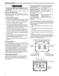
Figure 2 – Single Stage or Multi-Stage System
(No Heat Pump) with Single Transformer
System
RC
RH
C
Y
Y2
W/E
W2
G
O/B
6
L
Single Stage 1
(SS1)
Call for cool
No Output
Call for heat
Installer
Configuration
Menu selects
“O” or “B” for
changeover
function. Set
to “O” terminal
energized in Cool
& Off mode. Set
to “B” terminal
energized in
Heat & mergency
mode
No output
Fault or System
Malfunction
Indicator for
Heat Pumps
with “L” terminal
connection.
Original production
1F95-1291’s
do not have this
connection
24 volt
common
(optional
for system
operation,
required
for remote
sensor)
Blower/Circulator fan
energized on a call
for cool or Fan On
(also energized in
heating if configured
for Electric Heat)
Power closed
connection for
SPDT 3-wire
zone valve
24 volt
power for
cooling
24 volt
power for
heating
Cool mode-1st
stage
Heat mode-1st Heat mode-2nd
stage
stage
Multi Stage 2
(MS2)
Cool mode-2nd
stage
NEUTRAL
24VAC
HOT
120VAC
CLASS II
TRANSFORMER
SINGLE STAGE (SS 1) gas, oil or electric.
Single Stage and Multi-Stage Connections
Refer to equipment manufacturers’ instructions for specific system
wiring information.
MULTI-STAGE (MS 2) gas, oil or electric.
After wiring, see INSTALLER CONFIGURATION section for proper
thermostat configuration.
This thermostat is designed to operate a single-transformer or two-
transformer system.
You can configure the thermostat for use with the following fossil fuel
systems:
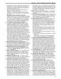
Figure 3 – Heat Pump Systems
System
RC
RH
C
Y
Y2
*W/E
*W2
G
O/B
6
L
Heat mode-2nd Heat mode-3rd
stage, Emergency stage, Emergency
Mode-1st stage
*Note: Dual Fuel
option de-
energizes Heat
mode stage 1
(compressor)
when auxiliary
Mode-2nd stage
*Note: Dual Fuel
option de-
energizes Heat
mode stage 1
(compressor)
when auxiliary
Heat
Pump 1
(HP1)
No Output
Installer
Configuration
Menu selects
“O” or “B” for
changeover
function. Set
to “O” terminal
energized in Cool
& Off mode. Set
to “B” terminal
energized in
Heat & mergency
mode
Fault or System
Malfunction
Indicator for
Heat Pumps
with “L” terminal
connection.
Original production
1F95-1291’s
do not have this
connection
24 volt
common
(optional
for system
operation,
required
for remote
sensor)
Blower/Circulator fan
energized on a call
for cool or Fan On
(also energized in
heating if configured
for Electric Heat)
Heat mode-1st
stage,
Cool mode-1st
stage,
(Compressor)
heat is energized heat is energized
Power closed
connection for
SPDT 3-wire
zone valve
24 volt
power for power for
cooling heating
24 volt
Heat mode-3rd
stage, Emergency stage, Emergency
Mode-1st stage Mode-2nd stage
Heat mode-4th
Heat
Pump 2
(HP2)
Heat mode-2nd
stage,
Cool mode-2nd
stage,
(Compressor)
*Note: Dual Fuel *Note: Dual Fuel
option de-
energizes Heat
mode stages 1
and 2 (both
option de-
energizes Heat
mode stages 1
and 2 (both
compressors) compressors)
when auxiliary when auxiliary
heat is energized heat is energized
NEUTRAL
NEUTRAL
24VAC
HOT
24VAC
HOT
120VAC
120VAC
COOLING
*Dual fuel option, if selected turns off compressor(s) when Auxiliary stages energize.
HEATING
CLASS II
TRANSFORMER
CLASS II
TRANSFORMER
HEAT PUMP TYPE 1 (HP 1). Single stage compressor system;
gas or electric backup.
Heat Pump Connections
If you do not have a heat pump system, refer to figures 3 & 4.
Refer to equipment manufacturers’ instructions for specific system
wiring information.
HEAT PUMP TYPE 2 (HP 2). Multi-stage compressor or two
compressor system with gas or electric backup.
You can configure the thermostat for use with the following heat pump
systems.
After wiring, see INSTALLER CONFIGURATION section for proper
thermostat configuration.
3
| General | Details |
|---|---|
| Name | OH-1202H Universal Humidity Touchscreen Thermostat Instruction Manual |
| Make | OH |
| Language | English |
| Filetype | PDF (Download) |
| File size | 0.42 MB |


EUROLAMP 147-44030 Digital Heating Smart Thermostat User Manual

TFC Group OP-WFSTAT Wi-Fi Programmable Thermostat User Guide

DELTA DORE Tywell 2050 Thermostat D’Ambiance Radio Installation Guide

COMFORT SENTRY OH-522 Programming Thermostat Instruction Manual

Generic HY610 WiFi Digital Heating Thermostat User Manual

OLIMPIA SPLENDID 9899 Thermostat User Manual

DIGITEN WTC100ZJ1 Remote Control With Thermostat Owner’s Manual

SIEMENS RDZ100ZB Zigbee Room Thermostat Owner’s Manual

Satel ART-210 Wireless Radiator Thermostat Instruction Manual

BEOK CONTROLS TDR89 Thermostat User Guide