Satel ART-210 Wireless Radiator Thermostat Instruction Manual


Wireless radiator thermostat
EN
ART-210
Firmware version 1.00
art-210_pl 07/24
SATEL sp. z o.o. • ul. Budowlanych 66 • 80-298 Gdańsk • POLAND
tel. +48 58 320 94 00

| General | Details |
|---|---|
| Name | Satel ART-210 Wireless Radiator Thermostat Instruction Manual |
| Make | Satel |
| Language | English |
| Filetype | PDF (Download) |
| File size | 0.47 MB |


Satel ART-200 Wireless Radiator Thermostat Installation Guide

Satel ART-210 Wireless Radiator Thermostat Instruction Manual Overview
Summary of Contents
- Page 1: Wireless radiator thermostat Firmware version 1.00
- Page 2: The device should be installed by qualified personnel. Prior to installation, please read carefully this manual. Changes, modifications or repairs not authorized by the manufacturer shall void your rights under the warranty. The device meets the requirements of the applicable EU directives. The device is designed for indoor installation. The device must not be disposed of with other municipal waste. The device meets the technical regulations of the Eurasian Customs Union. SATEL aims to continually improve the quality of its products, which may result in changes in their technical specifications and software. Hereby, SATEL sp. z o.o. declares that the radio equipment type ART-210 is in compliance with Directive 2014/53/EU. In the EU, this radio equipment is only permitted to operate in the 868 MHz frequency band.
- Page 3: Features Description LED display Knob Radio communication Energy saving mode (ECO) Battery status control Operating modes Thermostat calibration Installation Programming the settings
- Page 4: LED display is normally off. Touch the knob to turn on the display. The display shows temperature in degrees Celsius from the selected sensor. Symbols and messages are shown on the display. The display will turn off after 20 seconds of inactivity. Comfort temperature operating mode is displayed. Economy temperature operating mode is displayed. Open window has been detected and the valve is closed. Thermostat ready for calibration to be started. Low batteries, replace the batteries. Boost Heat is enabled, press and hold the knob to stop it.
- Page 5: Trouble with changing the valve position. Make sure the thermostat is mounted correctly on the valve and check the valve operation or restart the thermostat. Incorrect operating range of the thermostat may indicate a calibration failure. Ensure the thermostat is mounted correctly on the valve or restart the thermostat. Valve control may be disabled to protect against complete battery discharge if the battery voltage drops below 2.2 V. Replace the batteries. There may be a problem with the knob or a motor error. An internal error could prevent the valve from fully closing, indicating a calibration failure. Ensure the thermostat is mounted correctly on the valve or restart the thermostat. The ABAX 2 system may indicate no communication with the thermostat. Temperature is displayed in degrees Celsius. Valve position is displayed in percent, with 0P indicating the valve is fully closed and 100P indicating the valve is fully open. Pressing the knob turns on the display, changes the operating mode, or confirms new temperature settings or valve position. Pressing and holding the knob for 3 seconds can block or unblock the knob, edit temperature for the selected operating mode, or stop the Boost Heat.
- Page 6: Radio communication The thermostat connects to the controller at regular time intervals to provide information about its state. Additional communication occurs when the ART-210 thermostat sends manually adjusted settings to the controller. Energy saving mode (ECO) Enabling the ECO option prolongs battery life by reducing periodical communication to every 3 minutes. Battery status control The thermostat monitors battery voltage and displays a message when it drops below 2.3 V. If the voltage falls below 2.2 V, valve control is disabled to prevent complete discharge. Operating modes Comfort temperature mode maintains a comfortable room temperature and can be enabled remotely or manually. Economy temperature mode maintains an energy-efficient level and can also be enabled remotely or manually. Manual mode allows for temperature maintenance at a set level, with manual adjustments only. Thermostat calibration Calibration adjusts the actuator stroke to the radiator valve stroke and must be performed after installation or battery replacement. Thermostat adaptation The thermostat analyzes optimal valve positions for heating the room to the set temperature and adjusts accordingly based on changing conditions.
- Page 7: Boost Heat function enables faster heating by fully opening the valve for 15 minutes. The countdown to the end of the Boost Heat function will be displayed alternately with the temperature. The Boost Heat function has the highest priority, ignoring other functions and settings when enabled. Anti-scale protection prevents scale buildup by fully opening the valve once every two weeks. Open window detection interprets a sudden temperature drop as an open window, closing the valve for 30 minutes. Anti-freeze protection opens the valve when temperatures drop below 5°C to prevent freezing. Temperature measurement correction allows adjustment of the internal sensor's temperature information by ±3.5°C. Child Lock disables the knob to prevent accidental changes to settings. Improper handling of batteries can lead to explosion risks; follow manufacturer recommendations. The manufacturer is not liable for consequences from incorrect battery installation.
- Page 8: The used batteries must not be discarded, but should be disposed of in accordance with the existing rules for environment protection. The thermostat should be installed indoors, in spaces with normal air humidity. When selecting a place of installation, consider the radio communication range. Thick walls, metal partitions, etc. reduce the range of the radio signal. Use the ARF-200 tester to test the radio signal strength. The thermostat is fitted for radiator valves with the M30 x 1.5 mm threaded connection. In order to install the thermostat on the Danfoss RA, Danfoss RAV or Danfoss RAVL valve, use one of the provided adapters. The thermostat should be installed in such a way to ensure display visibility and knob accessibility. You do not need any special tools to install the thermostat. Before you remove the old thermostatic head, make sure to turn it several times from minimum to maximum position and back.
- Page 9: Replace the thermostat cover. The marks on the body and cover will help you replace the cover correctly. Mount the thermostat on the valve. Press the knob. The thermostat will be calibrated. Place the thermostat on the valve. Tighten the thermostat on the valve. If the thermostat is seated loosely on the valve, use the reducer ring. Unscrew the thermostat, place the reducer ring inside its flange, then repeat the mounting steps.
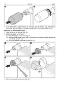
- Page 10: Mounting on Danfoss RA valve Fasten the adapter on the valve. Place the adapter on the valve. Bend open the adapter clamp with a screwdriver and press the adapter against the valve flange. Make sure the bumps inside the adapter line up with the notches on the valve body. Secure the adapter clamp with a screw. Place the thermostat on the valve. Tighten the thermostat on the adapter.
- Page 11: If the thermostat is seated loosely on the valve, use the reducer ring. Unscrew the thermostat, place the reducer ring inside its flange, then repeat the mounting steps. Place the cap on the valve pin. Fasten the adapter on the valve. Place the adapter on the valve. Bend open the adapter clamp with a screwdriver and press the adapter against the valve flange face. Secure the adapter clamp with a screw. Place the thermostat on the valve.
- Page 12: Tighten the thermostat on the adapter. If the thermostat is seated loosely on the valve, use the reducer ring. Mount the adapter on the valve. Place the thermostat on the valve. Tighten the thermostat on the adapter. If the thermostat is seated loosely on the valve, use the reducer ring. For description of how to program the thermostat settings, please refer to the ABAX 2 controller manual.
- Page 13: If you remove the batteries within 10 seconds since your last activity, the changes will not be saved. To change the operating mode, press the knob to turn on the display and keep pressing until the desired mode is displayed. The operating modes include comfort temperature and economy temperature. Temporary temperature settings will be used until the operating mode is changed. To set a new temperature, press the knob to turn on the display, display the current temperature, turn the knob to set the new temperature, and confirm the change. To change the selected operating mode settings, press the knob to turn on the display and keep pressing until the desired mode is displayed. Press and hold the knob for 3 seconds to edit the temperature or valve position. To start the Boost Heat function, press the knob and turn right. To stop the Boost Heat function before the end of 15 minutes, press and hold the knob for 3 seconds. To fully close the valve, press the knob and turn left.
- Page 14: Disabling the knob (child lock) allows you to block the knob when the LED display is turned off or shows temperature from the sensor. To disable the knob, press and hold for 3 seconds until a message appears on the display. Unblocking the knob is done by pressing and holding for 3 seconds, after which the temperature from the sensor will be displayed. Rotating the temperature/messages on the display requires removing the thermostat cover and batteries, then reinstalling the batteries and holding the knob for 5 seconds to rotate the message by 180°. Restoring the default settings involves removing the thermostat cover, removing the batteries, and holding the knob while reinstalling the batteries to start the LED display test. After the test is complete, release the knob, press it again, and then reinstall the batteries to show the message on the display. The operating frequency band is specified as 68.0 MHz to 868.6 MHz / 915 MHz to 928 MHz.
- Page 15: Radio communication range (in open area) ACU-220 up to 1000 m ACU-280 up to 500 m Batteries 2 x 1.5 V LR6 AA Battery life expectancy up to 2 years Standby current consumption 74 µA Temperature measurement range -10°C...+50°C Temperature measurement accuracy ±0.1°C Operating temperature range -10°C...+50°C Maximum humidity 93±3%

emos P5616OT Wireless Thermostat Instruction Manual

King K302PE ClearTouch Programmable Thermostat Instruction Manual

BEOK CONTROLS TCR7 IPS Colorful LCD Screen Smart Thermostat Owner’s Manual

WarmlyYours TH115-AF-GA-08 SmartStat TH115 Series Thermostat Instruction Manual

HERSCHEL MD2 Wi-fi Enabled Wired Thermostat Instruction Manual

GENERAL LIFE ARUNA 302S Wired Room Thermostat User Manual

Google Nest Learning Thermostat Installation Guide
ring Homeowner’s Pro Smart Thermostat User Manual

namron 4512737 Touch Zigbee 16A Thermostat Instruction Manual

Honeywell TH1100DH Non Programmable Thermostat Instruction Manual