OH-1202H Universal Humidity Touchscreen Thermostat Instruction Manual


WIRING DIAGRAMS
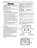
Figure 4 – Humidity and Sensors
+
-
HM
DHM
S
De-energizes on call for
Dehumidification to
lower the fan speed.
The DHM terminal is
only used on systems
with a compatible
dehumidification feature
that have the required
terminal connection on
the contol module or
have a relay installed to
lower the fan speed
Humidification Terminal,
Energizes on call for
heat if Humidity setpoint
is above room humidity.
Can also be used to
provide humidification
independent of a call for
heat and/or in cooling
mode if Automatic
Supply voltage
to remote
temperature
sensor
Supply voltage
to remote
temperature
sensor
Remote
temperature
sensor signal
Humidification is
selected in Configura-
tion Menu item #41
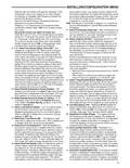
Dehumidification wiring without an electronically controlled variable speed blower system for
single stage compressor system only.
If you have a single stage compressor system see the dia-
gram below. A relay (customer provided) should be installed
as shown in Fig 7 to switch the fan speed to the next lower
speed on a call for dehumidification from the thermostat. The
reduction in air flow allows the coil to remove more humidity
from the air. The relay should be rated for blower motor load.
Since this configuration reduces the air flow in cooling, the
anti-freeze-up control (White-Rodgers CAFC) or equivalent is
recommended. The CAFC prevents the air conditioning coil
from freezing due to low air flow, dirty filters, low refrigerant
pressure, etc. The CAFC snaps onto the suction line close to
the evaporator coil as possible and breaks the compressor
circuit when the suction line drops below 38°F and re-make
the circuit at 46°F.
Figure 5 – Typical Wiring for Dehumidifier System
Normal High
DHM
No
Med
Relay
90-293Q
1
2
Low
or equivalent
Dehum
NC
Speed Fan
“Heat Fan Output”
N
“Cool Fan Output”
1
Normal Cool speed position (DHM energized)
2
Dehum speed mode (DHM de-energized)
N
Figure 6 – Typical Wiring for 120V Humidifier System
R
HM
Relay
90-290Q
or equivalent
HOT
24 VAC
120 VAC
NEUTRAL
HOT
TRANSFORMER
Humidifier
System
120 VAC
NEUTRAL
Figure 7 – Typical Wiring for 24V Humidifier System
R
HM
Humidifier
System
HOT
24 VAC
120 VAC
NEUTRAL
TRANSFORMER
4
| General | Details |
|---|---|
| Name | OH-1202H Universal Humidity Touchscreen Thermostat Instruction Manual |
| Make | OH |
| Language | English |
| Filetype | PDF (Download) |
| File size | 0.42 MB |


Robertshaw 4350 BJ Gas Thermostat Instructions

EpheyFIF WITH3 Wireless Gas Boiler Thermostat User Guide

WarmlyYours UTN5-4999 Thermostat User Guide

Aprilaire S86N MUPR Multi Stage Universal Thermostat Owner’s Manual

EUROTRONIC SPIRIT ZigBee Energy Saving Thermostat User Guide

tekmar U-T-562 WiFi Thermostat User Manual

COOKING PERFORMANCE GROUP 351030208 Retrofit Thermostat Instructions

Danfoss TP5001 Programmable Room Thermostat User Guide

GENERAL SENNA 300 Smart Room Thermostat User Manual

Wengart WG603 Home Smart Thermostat User Guide