Home > Micro-Air > Micro-Air 359 Touchscreen Thermostat Instruction Manual

Micro-Air 359 Touchscreen Thermostat Instruction Manual

EasyTouch  
359  
Operating Manual  
Revision 1.4  
1
©2023 Micro-Air LLC  
July 3, 2023, revision 1.4  
GeneralDetails
NameMicro-Air 359 Touchscreen Thermostat Instruction Manual
MakeMicro-Air
LanguageEnglish
FiletypePDF (Download)
File size0.5 MB
Download PDF
1 Star2 Stars3 Stars4 Stars5 Stars (1 votes, average: 5.00 out of 5)
Loading...
micro-air EasyTouch 357 Multi Zone Replacement Thermostat Instruction Manual
Micro-Air EasyTouch RV 353 Touch Screen Thermostat Instruction Manual
Micro-Air EasyTouch RV 353 Thermostat Instruction Manual
micro-Air EasyTouch RV 351 Thermostat User Manual
Micro Air ETRV EasyTouch RV Thermostat Instruction Manual
micro-air EasyTouch RV 356 True Air RV Thermostat User Manual
micro-Air ASY-357-X02 EasyTouch 357 Touchscreen Thermostat User Manual
micro-Air EasyTouch 352 Thermostat User Manual
Micro-Air EasyTouch 355 Touch Screen Thermostat User Manual
Micro-Air 351 Air Conditioner Digital Thermostat User Guide

Micro-Air 359 Touchscreen Thermostat Instruction Manual
Get the free PDF manual for the Micro-Air 359 Touchscreen Thermostat Instruction Manual and access setup steps, usage instructions, and troubleshooting tips. 👉 View online or download now to keep your thermostat running smoothly!

Micro-Air 359 Touchscreen Thermostat Instruction Manual Overview
Summary of Contents

  • Page 1: Operating manual Revision 1.4 ©2023 Micro-Air LLC July 3, 2023, revision 1.4
  • Page 2: Safety first Installing the thermostat Removing the old thermostat Wiring the thermostat Thermostat setup Operating the thermostat Schedule screens Settings screens Troubleshooting Appendix
  • Page 3: Wiring the thermostat Safety first: Turn off power to the air conditioner breaker and to the 12-volt circuit powering the thermostat. Use the table entries written in Table 1 to complete the wiring. Insert each wire as described in the section titled Using the push button terminals. Remove power before changing the control box wiring. Identify the red and red/white wires exiting the control box. Remove the wire connected to the red/white wire which may still have the label “To T-Stat 7.5 Screw.” Add the wire disconnected in step 2 to the +12-volt wire connections. The goal is to identify which of these 4 wires goes to the original thermostat’s +7.5 terminal. You should have ultimately a wire by itself (the control box outgoing +7.5 wire) and the other three altogether.
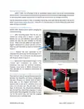
  • Page 4: Mounting the thermostat involves several steps. Locate the mounting buttons horizontally across the hole with the smaller diameter against the wall. Screw in one screw and level the buttons so the display will be straight when installed. Screw in the second screw making sure the two buttons remain level. Remove the mounting tab before mounting on the wall. Align the buttons with the holes in the back of the display. Press the display against the wall and gently slide the display down to lock it in place.
  • Page 5: Thermostat setup involves pressing the settings button on the main screen and using the back and next buttons to locate the switches icon for mode configuration. Gas heat override can be enabled or disabled by tapping the button under the Auto Gas Changeover heading, with most users leaving this setting enabled. The valve output setting determines whether the system operates in Active Heat or Active Cool, and is typically set during installation. Furnace output can be set to either inverted or normal, affecting how the thermostat activates the furnace. Most users will set the furnace output for inverted, ground active output, and this setting should match the furnace's requirements. EasyTouch RV can be operated via the touchscreen or remotely using the EasyTouch RV application, which allows for wireless communication and operation modifications. Some features of the EasyTouch RV application require a wireless connection, detailed in the section on working wirelessly.
  • Page 6: Operating the thermostat Main screen This screen allows you to set and monitor the desired operation of the thermostat. Inside temperature This is the temperature reading for the space that the thermostat is trying to temper. Local weather This icon indicates the local weather at the last time weather information was received. Status tray Various icons may indicate active operations, including the Wi-Fi indicator. Status message Various messages may be shown to indicate active operations. Temperature set point adjust Raise and lower the temperature set-point using the red and blue arrows. Operational mode All modes are listed in the operational mode section.
  • Page 7: System power is controlled by a button that indicates on (green) or off (red). Pressing the mode button changes the current operating mode, with options including cool only, furnace only, aqua only, auto modes, heat pump only, fan only, and heat strip only. If a mode is missing, refer to the section on setting the available sources. The fan button selects the fan operation mode, with options for fan low, fan high, fan off, and fan auto. Fans with green bars indicate manual operation, while fan auto adjusts speed based on temperature differences. Pressing the settings button opens the settings screen for additional configurations. The additional status tray may display icons indicating active operations, such as an hourglass symbol for heating or cooling cycle delays. The hourglass icon indicates a 3-minute timer before a new cycle starts. The outside temperature reading is retrieved via the thermostat’s internet connection and is part of the local weather information.
  • Page 8: Operational modes operate the overhead fan and/or a heating or cooling cycle based on the current heating or cooling setpoint, relative to the inside temperature. Fans and Fan Only Mode allows the fan to operate based on the chosen fan speed, circulating air without heating or cooling cycles. Cool Only Mode runs a cool cycle to maintain the cooling set-point in the space. Heat Strip Only Mode runs an electric, overhead, heat pump or heat strip heating cycle to maintain the heating set-point in the space. Table 2 outlines the operation for Cool Only Mode, which may vary based on the gap settings. Table 3 outlines the operation for Heat Pump and Heat Strip Only Mode, which may also vary based on the gap settings. These heat modes are subject to Gas Heat Override Operation when enabled.
  • Page 9: Furnace Only or Aqua Only Mode Aqua Only Mode runs an auxiliary heating cycle to maintain the heating set-point. Set the Operational Mode button to Furnace Only or Aqua Only and the desired Fan Speed. Furnace Only Mode includes various operational parameters such as cycle operation and auto fan operation. Table 4 outlines Furnace Only Mode operation, which may vary based on Gap settings. Auto Modes automatically switch between heating and cooling cycles as needed. Auto modes have separate heating and cooling set-points. No heating or cooling cycles will occur when the inside temperature is between the set-points. Auto modes are subject to Gas Heat Override and Gap operations. Press the set-points to toggle between selected set-points, indicated by a blue square. Use the up and down arrows to change the selected set-point value.
  • Page 10: Gas Heat Override operation is an algorithm for calling for additional stages of heat when the thermostat determines more are needed. The two escalating stages are shown in Table 5. This logic is disabled when both stages are not available. Table 6 shows how Gas Heat Override affects the heat pump and heat strip operational modes when enabled. Normal heating operation occurs when inside temperature is 4° or less below setpoint. Stage 1 and Stage 2 runs until setpoint is satisfied when inside temperature is 5° or more below setpoint. Stage 2 starts and runs any heat cycle for the next two hours. Three cycles in a row call for escalation, with Stage 1 locked out during this time. Operation may be different based on the Gap settings. See section Temperature Gap (Hysteresis) for details.
  • Page 11: Local weather is displayed on the main screen. Tapping the button will reveal more detailed weather information. A valid location and an internet connection on the thermostat are required to retrieve weather data. Location is saved in the thermostat when a Bluetooth connection is made from a smart device. New weather data is retrieved when there is a screen press or when a connection from a smart device is made. Time is pulled in when a Bluetooth or Wi-Fi connection is made from the app. Status messages may be displayed on the main screen. The room sensor inside EasyTouch RV has failed open/disconnected or shorted and must be repaired. AUX heat enabled means that the two-hour timer of the Gas Heat Override logic is active. Table 7 shows the potential messages and their meaning.
  • Page 12: The schedule supports 7 day per week scheduling of events. Events can include changes to the set point or mode of operation for one or more zones. The smart device application also offers a method to copy days. Once a schedule is set for one day, it can be copied to any other day. Day of the week is selected from the days along the top of the screen. The day selected appears in white. Events are numbered 1 to 6 along the left side of the display. Tap an event to edit it and advance to the schedule edit screen. System time is displayed along the bottom. Tap the time to change from 12-hour to 24-hour time format. Tap the back arrow to return to the last screen.
  • Page 13: Figure 7 shows the edit screen when an event is tapped on the main schedule screen. The event and action time in the edit screen will show disabled until a time is set. Press “Disabled” at the top of the screen to show a gray box around the disabled selection. Use the up and down arrows to make a change. The arrows change to full color once a selection is made. Use the back arrow to save any changes and leave the screen. Figure 8 shows the schedule edit screen once a valid time is set for the event. Set the event time by selecting hours, minutes, or AM/PM. Set the desired mode by tapping the mode button. Tap the hours, minutes, AM/PM, or the set point to select an editable parameter, then use the red and blue arrow buttons to make a change. Tap the zone number to enable or disable the zone you want this event to affect. A green box will draw around zones the event is enabled for. Create and enable a schedule by tapping the edit schedule button to enter the main schedule screen. Ensure that a valid system time is shown. Tap the day you want to set up a schedule for, then the event you want to edit. Tap the Action Time, Setpoint, and Mode to make edits to what you want your event to do. Tap the zone you want this event to occur in if shown. Tap the back button and repeat for any other events and any other days. Tap the back button once again to return to the settings screen and this will save your schedule. Activate the schedule by pressing the schedule button with the “Enabled/Disabled” subtext. When enabled, it will be noted on the Main Screen Status Tray.
  • Page 14: Settings screens allow for further configuration and control of the thermostat. It is a paged system that you can navigate through to see all available settings. Not all settings may be available based on your EasyTouch RV model. Tap the settings button to view them. Use these buttons to flip through all the available settings or return to the main screen. This screen displays a QR code that can be scanned to provide information about thermostat operation and troubleshooting. Tap the icon to switch between Day or Night mode. This screen allows you to set the Active and Sleep brightness levels. Tap the enable/disable button to turn the schedule on or off. This screen allows you to monitor the state of your Wi-Fi connection to the thermostat.
  • Page 15: Bluetooth password reset is used to match your EasyTouch RV app account for remote connections. Only one account can access the thermostat. Temperature reading adjustment allows calibration of the inside temperature reading with an offset. Temperature gap settings determine the difference in temperature required for heating or cooling cycles to begin. The auto-fan high setting determines the temperature difference required for the fan speed to switch from low to high. Measurement units setting allows toggling between Fahrenheit and Celsius for temperature display.
  • Page 16: Touchscreen calibration is set at the factory but can be recalibrated using the Touchscreen Calibrate Button. Pressing the Restart button will turn the thermostat off and on, simulating a power cycle. The Reset All setting restores certain thermostat settings to factory defaults, with options for specific resets. Dip switches configure the thermostat's operational settings, varying by EasyTouch RV model. The Auto-Generator Start (AGS) setting allows a generator to start before appliances needing line voltage and stop afterward. The AGS Enable button toggles this feature on or off. Furnace/Aqua icons represent auxiliary heat modes, with a button to toggle the display for operational modes. This setting is cosmetic for most EasyTouch RV models, except for the 350 model, which requires appropriate configuration. Refer to the Thermostat Setup section for configuration details. Micro-Air cannot assist with adding more appliances to the system.
  • Page 17: Smart device settings options Reset device This Bluetooth only feature allows resetting the display just as if you removed and restored power. Calibrate touchscreen It is normally not necessary to recalibrate the touchscreen. This selection prompts the user to press the four corners of the display then test the calibration using three diagonal marks. Check for updates Checks to see if any updates are available for the thermostat. The smart device application must have internet and the thermostat must be connected to Wi-Fi with a green Wi-Fi symbol. Notifications Notifications provide a way for the user to monitor the temperature in the space using notification limits. Limits are set by connecting to the thermostat in the app, selecting the settings gear, and then selecting notifications. Edit Wi-Fi settings or connect to Wi-Fi This is where you will make the connection from the thermostat to the internet. The app must be connected to the thermostat over Bluetooth to see this option.
  • Page 18: Troubleshooting common problems during installation includes mismatching wires and improper seating of wires in the connector. Always recheck the instructions to ensure proper wire seating. Understanding thermostat operation is crucial; large numbers indicate heating or cooling cycles with color changes. When the thermostat numbers turn white, the heating and cooling systems should be off, but the fan may continue running. Check the fuse on the back of EasyTouch to verify it is functioning. A table shows the terminal label and purpose for each thermostat wire, aiding in troubleshooting. Use a voltmeter to verify if the thermostat has activated an EasyTouch output. Correct voltages indicate the thermostat is functioning, but further troubleshooting may be needed if outputs are not operating. If the thermostat lacks power, test between the R and B wires for 12-volt power. Visit the knowledge bank for resources on setup, operation, and troubleshooting.
  • Page 19: Working wirelessly This thermostat may be operated remotely using either Bluetooth or Wi-Fi. All connectivity is performed through the EasyTouch RV App on a smart-device. Bluetooth is a limited range method to connect, typically used when near the thermostat. If a second user is going to use the thermostat remotely, they must use the same account and password that the first user assigned to the thermostat. EasyTouch RV uses BLE which is a special implementation of Bluetooth. An internet connection on your smart device is necessary for these steps. Once the account is created, the application may ask to add a device. Enter your SSID (network name) and password of the network you want to connect the thermostat to. Follow the next steps if the account process does not add a control or a second thermostat is to be added.
  • Page 20: Connecting to a new Wi-Fi network allows you to control the thermostat from anywhere using the app. The internet source must be a 2.4GHz network to connect to EasyTouch. To connect, use Bluetooth to access the settings and select Wi-Fi Setup. Choose a network from the available options or enter the SSID manually. Enter the password, which is case sensitive, and press OK. A green Wi-Fi symbol indicates a successful connection, enabling app access from anywhere. Updating the EasyTouch RV thermostat ensures you have the latest features. Confirm the thermostat is connected to Wi-Fi with a green symbol before checking for updates. Follow the prompts to update or verify the software version.