
seitron Wi-Time Wall Wi-Fi Programmable Thermostat Instruction Manual












WIRING DIAGRAM
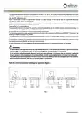
The programmable thermostat wi-time wall can be powered at 85..264 V 50..60 Hz. The L and N terminals power the programmable thermostat
at 85..264V and are to be connected to the mains voltage with the neutral on the terminal N. Terminals 1, 2 and 3 are the contacts, voltage
free, type SPDT of the output relay.
Figure 1 illustrate how to connect the programmable thermostat to a boiler. The boiler will be turned on when the programmable thermostat
associated with output asks for heat (heating mode).
On Figure 2 it is shown how to connect a load (for example a pump) which is powered when the output is active and that is when the programmable
thermostat requires heat (heating) using the NA relay terminal.
Follow the Fig. 1 or 2 connection diagram.
The programmable thermostat has an input for connecting a remote probe (optional). In case the installation includes a remote probe mounting, it is
necessary to connect a 10 kΩ NTC-type probe at 25°C to terminals 6 and 7.
If in doubt about the type of probe to be connected, please consult the manufacturer.
The device can be connected to a home automation control unit with which it will communicate via RS485 bus with MODBUS® RTU protocol. The
RS485 bus is available at terminals 9 (A) and 8 (B).
The signals relating to the RS485 port are insulated with double insulation in relation to the power supply terminals L and N and the output relay
termin
It is necessary to tie toghether the cable groups with cable ties separating the power and load wires from those of the bus to avoid that if a wire
is accidentally disconnected, this does not reduce the electrical insulation.
For more information on the operating mode and the communication protocol, it is necessary to contact the local dealer.
WARNING
- To adjust properly room temperature, install the programmable thermostat far from heat sources, airstreams or particularly cold walls
(thermal bridges). If a remote probe is used, the note should be applied to the probe and not to the thermostat.
- If the load driven by the programmable thermostat works with mains grid power, it is necessary that the connection is performed
using an omnipolar switch complying with the current standards and with a contact opening distance of at least 3 mm in each pole.
- The installation and electrical connections of the device must be carried out by qualified personnel and in compliance with current standards.
- Before making any connections, make sure that the power supply is disconnected.
Make the electrical connections following the appropriate diagram.
Fig. 1
Fig. 2
GCW03MR001SE 040088 230922
5

| General | Details |
|---|---|
| Name | seitron Wi-Time Wall Wi-Fi Programmable Thermostat Instruction Manual |
| Make | seitron |
| Language | English |
| Filetype | PDF (Download) |
| File size | 0.32 MB |
 (1 votes, average: 5.00 out of 5)
 Loading...

seitron TAD022 Digital Room Thermostat for Heating Cooling System Instruction Manual

seitron TM 00-M Electro Mechanical Room Thermostat Instructions

seitron 039790 WiFi WiTime Wall Programmable Thermostat User Guide

seitron DR R02M Thermostat Wireless Kit Instruction Manual

seitron KTY003 Hygge Kit Class 5 WiFi Battery Powered Programmable Thermostat User Guide

seitron TR D02B Wireless Digital Thermostat User Manual


CENTER EHE0200322 RF Wireless 7 Day Programmable Thermostat Installation Guide

WYZE WTMSRS 3-in-1 Digital Room Sensor for Smart Thermostat User Manual

STEGO ET 011 Electronic Thermostat User Manual

RITTAL SK 3114.200 Digital Enclosure Internal Temperature Display and Thermostat Instructions

White Rodgers 1F78-151 Non Programmable Thermostat Instructions

GENERAL LIFE 270S RF Room Thermostat User Manual

Netatmo NTH01-AMZ Energy Saving Smart and Connected Thermostat Instruction Manual

GENERAL FH25S Underfloor Heating Thermostat Owner’s Manual

LUXPRO PSD111+ Series Thermostat Instruction Manual

Jung FTR231 Floor Thermostat Instruction Manual