
seitron DR R02M Thermostat Wireless Kit Instruction Manual
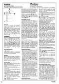
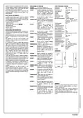
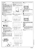
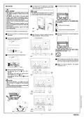


To factory reset:
- Power down
- Press and hold both buttons
- Power on
- Wait until the LEDs blink
- Release the buttons
TROUBLESHOOTING
TECHNICAL FEATURES
Power supply:
Absorption:
Relay contacts ratings:
Regulation hysteresis :
Frequency:
230V 50Hz / 24V
11VA
2 x 6(4)A 250V (voltage free)
0,3°C
868,150 MHz
-105 dBm
GFSK
SYMPTOM:
The receiver appears completely “dead”.
and
Fig.1
A
B
PROBABLE CAUSE: There’s no mains power.
REMEDY:
Check the mains power connection.
Usually LEDs may remain off, but they
perform blinking sequence “green-red-
a
Sensitivity:
Modulation:
REGULATION WITH DEAD BAND
The receiver can be set on jumper JP1 to regulate with dead band
(see step 7 under "Installation").
When regulating with dead band, the receiver drives the “heat”
valve with the relay of channel 1 and the “cool” valve with the
relay of channel 2.
green-red” when the receiver is switched on
to indicate correct operation.
Bandwidth (-3 dB):
Type of antenna:
Max. distance from transmitter: >300m in free field
>50 m in buildings (depending
100 KHz
internal stylus
SYMPTOM:
One of receiver’s LED continuously blinks
green.
PROBABLE CAUSE: The device is signalling a fault because it
has detected an error in the temperature
probe of the wireless thermostat or
programmable thermostat.
on the building and environment)
IP 3X
1
II
2
When regulating with dead band, the receiver can learn only one
thermostat on channel 1 and the thermostat will drive both relays
of channel 1 and channel 2. If the setpoint temperature is greater
than the room temperature there is a “heating” request and the
“heat” valve on relay 1 will be turned on, conversely, if the
setpoint temperature is lower than the room temperature there is
a “cooling” request and the “cool” valve on relay 2 will be turned
on. If the room temperature matches the setpoint temperature
both outputs remain off. More in detail the width of the dead band
determines the temperature range in which the outputs remain
off. The dead band‘s width can be set on the trimmer with a small
screwdriver in the range 1 to 11 °C (see step 8 in "Installation").
The heating output will be activated when the room temperature
is below the setpoint temperature of half the dead band, while the
cool output will be activated when the room temperature will be
higher than the temperature setpoint of half the dead band.
When in dead band regulation it is assumed that the heating and
cooling systems are always available and the heating/cooling
status of the transmitter will be ignored, as it is the room
temperature that will determine whether to heat or to cool.
When in dead band regulation, the “test” mode of the thermostat
will toggle every 2 seconds only output 1 (heating).
Protection rating:
Type of action:
Overvoltage category:
Pollution degree:
Tracking index (PTI):
Class of protection
against electric shock:
Rated impulse voltage:
Number of automatic cycles:
REMEDY:
Check the temperature probe of the
transmitter and, if present, the jumper for
selecting between the internal and external
probe. Carefully read the instructions of the
transmitters for further information.
175
II
2500V
SYMPTOM:
One of receiver’s LED continuously blinks
yellow.
100000 (diagrams on Fig. 7, 8,
9, 10)
A
230V 50Hz
45 mA
PROBABLE CAUSE: The device is signalling a fault because it
has detected the wireless thermostat or
programmable thermostat batteries to be
running low.
Software class:
EMC test voltage:
EMC test current:
Distances tolerances fault
mode ‘short’ exclusion:
REMEDY:
Replace the batteries of the transmitters
concerned. Carefully read the instructions of
the transmitters for further information.
±0,15 mm
Ball pressure test temperature: 75 °C
Operating temperature:
Storage temperature:
Humidity limits:
Enclosure: Material:
Colour:
0°C .. 40 °C
-10°C .. +50 °C
20% .. 80 % RH non-condensing
ABS V0 self-extinguishing
Signal White (RAL 9003)
(RAL 9003)
SYMPTOM:
One of receiver’s LED continuously blinks
red.
PROBABLE CAUSE: The channels in question are in an “alarm
status” due to the absence of radio
communication.
When the receiver is set for dead band regulation, it can not
perform the lower and upper floor temperature limitation that can
be set on TRD01B and DCW01B thermostats.
Installation:
Wall mounted
REMEDY:
Check the radio communication again using
the “test” function on the transmitter.
Assess whether the devices need to be
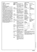
DIMENSIONS
moved away from metal shields or
“repeater” needs to be installed.
a
SYMPTOM:
When starting the self-learning procedure,
the receiver does not blinks the LED yellow.
PROBABLE CAUSE: The self-learning button has been pressed
too quickly.
REMEDY:
Start the self-learning procedure keeping
pressed the self-learning button for one
second.
SYMPTOM:
The transmitter is in the “test” mode but
the receiver fails to switch on any relay.
The LED does not indicate any reception of
commands via radio.
WARRANTY
PROBABLE CAUSE: The signals received are too weak to enable
In the view of a constant development of their products, the
manufacturer reserves the right for changing technical data and
features without prior notice.
correct decoding of the commands .
REMEDY:
Assess whether the devices need to be
moved away from metal shields or
“repeater” needs to be installed.
a
The consumer is guaranteed against any lack of conformity
according to the European Directive 1999/44/EC as well as to the
manufacturer’s document about the warranty policy. The full text
of warranty is available on request from the seller.
SYMPTOM:
The receiver’s LED remain red despite the
communication with the transmitter had
been restored.
PROBABLE CAUSE: The long-term analysis of the signal quality
reports the history of the last 90 minutes of
the channel activity.
REMEDY:
Verify with the “test” mode that the
“immediate” indication on the LED indicates
a sufficient signal quality and allow up to
90 minutes for the long-term analysis to
turn green.
6
- ENGLISH -

| General | Details |
|---|---|
| Name | seitron DR R02M Thermostat Wireless Kit Instruction Manual |
| Make | seitron |
| Language | English |
| Filetype | PDF (Download) |
| File size | 0.56 MB |
 (1 votes, average: 5.00 out of 5)
 Loading...

seitron Wi-Time Wall Wi-Fi Programmable Thermostat Instruction Manual

seitron TAD022 Digital Room Thermostat for Heating Cooling System Instruction Manual

seitron TM 00-M Electro Mechanical Room Thermostat Instructions

seitron 039790 WiFi WiTime Wall Programmable Thermostat User Guide

seitron KTY003 Hygge Kit Class 5 WiFi Battery Powered Programmable Thermostat User Guide

seitron TR D02B Wireless Digital Thermostat User Manual


SAUTER 396011 Universal Thermostat Owner’s Manual

GENERAL LIFE 300S Wired Room Thermostat User Manual

BEOK BOT-T9N-WIFI Desktop Type RF Smart Thermostat for Wall-Hung Boiler User Manual

Ensto ECO16BT-IN-WW Floor Heating Thermostat User Guide

TELLUR TLL331431 WiFi Smart Ambient Thermostat TSH02 User Manual

Honeywell TH4110U Thermostat Installation Guide

Honeywell RTH2510/RTH2410 Thermostat Installation Guide

Honeywell Y460A2003 Creative Series Thermostat Installation Guide

ADAX VG11 Digital Thermostat User Guide

Danfoss AN325057 Icon Wireless Room Thermostat Installation Guide