
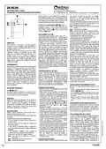
seitron DR R02M Thermostat Wireless Kit Instruction Manual
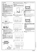
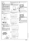
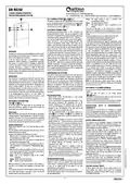
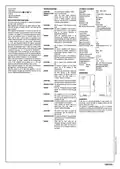


Fix the plate onto the wall using the two screws housings
with a 60 mm centre-to-centre distance (use the screws
and/or dowels supplied) - Fig. 6.
Set JP1 jumper if the “dead band” regulation is desired.
INSTALLATION
5
7
WARNING!
WARNING
- When deciding on a correct position, make sure that the
radio signals transmitted are received correctly by the
receiving unit.
-
The receiver must be installed on a wall or on a surface
in order to make the back of the product inaccessible.
- The appliance must be wired to the electric mains
through a switch capable of disconnecting all poles in
compliance with the current safety standards and with a
contact separation of at least 3 mm in all poles.
- The 24V power unit must be featured with an overload
protection.
Fig. 11
THE JP1 JUMPER ALLOWS TO SET THE WORKING MODE
OF THE RECEIVER:
- Device installation and electrical connections must be
carried out by qualified personnel and must comply with
the laws in force.
- Before making any connections, make sure the mains
power is disconnected.
A
Two channels receiver (default).
B
A
One channel receiver with dead band regulation.
B
Fig. 6
To install the device it is necessary to access the internal parts.
Set the dead band width trimmer if dead band regulation has
been chosen.
Make sure that the device is not powered (no mains power
supply applied).
8
1
Make the electrical connections following the appropriate
diagram and paragraph " Electrical connections ".
6
Using a screwdriver, push the plastic flap of the bottom slot
and slightly lift the cable lid up (Fig. 2).
Reinforced insulation
2
Fig. 12
THE DEAD BAND WIDTH CAN BE SET WITH A SMALL
SCREWDRIVER IN THE RANGE 1÷11°C .
Fig. 2
Rotate the cable lid and remove it completely (Fig. 3).
3
Fig. 7
Place the cable lid on the base and rotate it towards the
base; push the cable lid until the locking plastic flap springs
into the hole on the lower side of the cable lid (Fig. 3).
9
Configure the device as described in the paragraph
“Configuring the system”.
10
Fig. 3
There are three options for the cable entry:
4
Back cable entry: Open the hole
screwdriver.
Fig. 5, with a
E
Side cable entry: With suitable pliers, remove the plastic
teeth, as indicated by arrows in Fig. 4.
Fig. 8
D
Bottom cable entry: Open one or both holes
a screwdriver.
Fig. 5, with
F
WARNING
-
-
When working with tools in the vicinity of the screw
holes, be careful not to damage the internal electronic
circuits.
The chosen cable entry and the removal of plastic teeth
may modify the IP grade of the product.
Fig. 9
D
D
Fig. 4
E
F
F
Fig. 10
Fig. 5
4
- ENGLISH -

| General | Details |
|---|---|
| Name | seitron DR R02M Thermostat Wireless Kit Instruction Manual |
| Make | seitron |
| Language | English |
| Filetype | PDF (Download) |
| File size | 0.56 MB |
 (1 votes, average: 5.00 out of 5)
 Loading...

seitron Wi-Time Wall Wi-Fi Programmable Thermostat Instruction Manual

seitron TAD022 Digital Room Thermostat for Heating Cooling System Instruction Manual

seitron TM 00-M Electro Mechanical Room Thermostat Instructions

seitron 039790 WiFi WiTime Wall Programmable Thermostat User Guide

seitron KTY003 Hygge Kit Class 5 WiFi Battery Powered Programmable Thermostat User Guide

seitron TR D02B Wireless Digital Thermostat User Manual


STEGO FTO Preset Thermostat User Guide

DAIKIN DTST-ONE-ADA-A One Touch Smart Thermostat Installation Guide

ideal BOILERS Combi RF Wireless Boiler Thermostat User Guide

Honeywell Home TH2110DH 1 Cool Programmable Digital Thermostat Installation Guide
ENERGY TK02 Electronic Thermostat for Warm Floor User Manual

ADVENT AIR ACTH12 Digital LCD Thermostat Instruction Manual

EcoNet RETST800SYS Smart Thermostat User Guide

FC610 Bandary Smart Thermostat Owner’s Manual

Honeywell TC500A-N Commercial Thermostat User Guide

Danfoss UT 72-UT 73 Universal Thermostat Installation Guide