
seitron DR R02M Thermostat Wireless Kit Instruction Manual
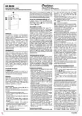
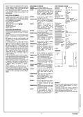
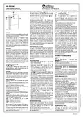


DR R02M
2 RADIO CHANNELS RECEIVER
FOR HEATING/COOLING SYSTEM
Via del Commercio, 9/11 36065 Mussolente (VI)
C
SELF-LEARNING BUTTONS (
The device is equipped with two self-learning buttons for setting
up the wireless link between the thermostat (or programmable
and
B
Fig. 1)
Green: The signal received is good or excellent, radio
communication is reliable.
Yellow: The signal received is sufficient.
A
Red:
The signal received is weak, communication is not
reliable.
thermostat) and the receiver, one button for channel 1
Fig. 1
A
and one button for channel 2
Fig. 1.
B
A
B
The status of the output of the actuator that is currently
switched off is signalled with the corresponding LED faintly lit
rather than off, so that the quality of the radio signal can always
be seen.
The receiver indicates two types of signal quality on the LED:
- An immediate analysis of the last command received;
D
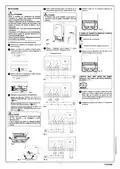
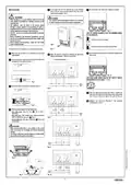
ELECTRICAL CONNECTIONS
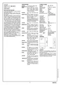
The device can be powered at 230V or 24V . Terminals L and
N supply the receiver at 230V and must be connected to mains
with neutral to terminal N. Alternatively connect the power supply
to terminals a and N to power the device at 24V . Terminals 1, 2
and 3 are the voltage free SPDT relay contacts of the channel 1
output. Terminals 4, 5 and 6 are the voltage free SPDT relay
contacts of the channel 2 output. Figure 7 and 9 shows how to
connect a valve that will be powered when the output is set and
that is when the thermostat calls for heat (heating) using the NO
contact of the relay. Figure 8 and 10 shows how to connect to
the receiver a heat valve and a cold valve when the receiver is set
for regulation with dead band. The outputs, terminals 1 to 6, are
voltage free and insulated with reinforced insulation towards the
other circuits of the receiver. Therefore, the receiver can be
supplied with SELV low voltage (24V ), while controlling a high
voltage load (230V ), as shown in Fig. 9 or 10. In this case 24V
SELV and 230V cables must be separated complying with current
standards. In particular, it is necessary to secure the two groups of
cables with cable ties separating the SELV wires from the others.
This is required to avoid that the insulation to SELV is reduced in the
event of a wire accidentally disconnects.
- A long-term analysis of the commands received.
The LED will normally indicate the “long-term” signal quality, based
on the quantity of correct commands received over the previous 90
minutes of operation. In case no command has been received from
the transmitter in the last 90 minutes, the LED will stop showing
the "long-term" analysis and will blink red to show the "absence
of radio communication" fault condition. The signal quality
analysis is non-volatile memorized, so it is possible to evaluate the
channel communication status also after a power cycle. In the
moment a radio command is received, the output LED goes off for
a brief instant and then immediately back on again. For a brief
instant the LED will provide an immediate indication of the last
command received, proportional to the strength of the radio signal
received. If a transmitter is in the “test” mode, the LED on the
receiver will always provide only an “immediate” indication so that
you can instantly assess whether to go ahead with mechanical
installation. If the signal strength is not acceptable try to change
the position of the receiver or transmitter or evaluate the
possibility to install a repeater device (DAPF84) which doubles the
range of the radio commands. Remember that both the transmitter
and receiver must be installed away from metal objects or metal-
reinforced walls that could weaken the radio signals.
Fig. 1
OVERVIEW
This device is a two channels receiver designed to switch on loads
(more precisely, electro-thermal valves or circulators) via radio in
home or office heating/cooling systems.
It has two channels that have to be associated to relevant
transmitters, wireless thermostat or programmable thermostat.
This system is an optimal solution for buildings in which wires
cannot be laid between thermostats and the environment to be
controlled. Operating on a frequency of 868.150 MHz (LPD)
provides the user with all the advantages of this band, such as the
greatest freedom from interference and greater efficiency in the
transmission of the signal.
CONFIGURING THE SYSTEM
To be able to install several thermostats in the same area and to
be able to use the multichannel systems, every thermostat is
equipped with its own address code. Thermostats with different
addresses can work at the same time without interfering each
other and therefore controlling different areas. To memorize the
address of the thermostat from which we want to receive the
signals in the receiver, it is necessary to perform the self-learning
procedure described below. It is possible to repeat several times
the self-learning procedure, the new address will overwrite the old
one stored.
OPERATION
Each thermostat or programmable thermostat transmitter sends
radio commands to the receiving unit based on the heating and
cooling requirements of the room where it is located. These radio
commands are then received and decoded by the receiving unit,
which is usually installed in the same room as the boiler or air
conditioning equipment. The relay outputs are turned on or off in
the receiving unit depending on the requirements. These output s
can be connected to valves that control the flow of hot/cold water
in the heating/cooling unit located in the room. While it is
operating, the receiver continuously monitors the status of each
channel in order to detect any transmitter malfunctions.
NOTE: The LED may blink to signal a system fault. In this case
the colour of the LED has a different meaning, see the paragraph
on “Actuator outputs status”.
DELETION OF A LEARNED ADDRESS
In case you want to delete the address learned on one of the two
channels:
- Press and hold the button of the desired channel
Self-learning procedure
- Switch on the receiver: the LEDs blink for a few seconds
during the initialisation phase.
(
or
Figure 1).
A
B
- The relevant LED flashes quickly in yellow and after a few seconds
will flash in a sequence red-green-red-green.
- Release the button, the channel is now inactive. When a channel is
'inactive' on its LED and relay output will remain permanently off.
- Turn on the thermostat or programmable thermostat in “test”
mode, then the transmitter will continuously send an ON
command followed by an OFF command after two seconds.
Turn on only one thermostat in the “test” mode at a time. It is
advisable to keep the transmitter in the same room of the
receiver, apart at least one meter each other.
MECHANICAL DESCRIPTION
LEDs (
and
Fig. 1)
C
D
On the front panel of the device there are two multicolor LED
which gives information regarding the correct power supply, the
output relays status and the signal strength:
ASSOCIATION WITH
THERMOSTAT
A
PROGRAMMABLE
The association of a channel driven by a thermostat to a channel
driven by a programmable thermostat is not possible in this product.
If one of the channels is controlled by a programmable thermostat,
the heating/cooling setting of the programmable thermostat will be
extended to the other channel if it is controlled by thermostat.
- Press the self-learning button of the desired channel for a
Power supply
second
Fig.1 for channel 1 and
Fig.1 for channel 2. The
A
B
When the receiving unit is powered, the LEDs light up and perform
a blinking sequence “green-red-green-red” to indicate the correct
operation of the device. Then the LEDs becomes active depending
on their normal operation and the receiver starts to perform its
normal activity, decoding the signals sent by the transmitters.
self -learning procedure starts: the relevant channel’s LED will
blink quickly yellow.
- As soon as a test command is received, the LED will remain
steadily lit yellow for 7 seconds. During this time the receiver
will continue to receive test commands and memorize only the
signal received with the highest strength. This means that it
will memorize the signal coming from the nearest transmitter
and will thus avoid learning addresses from any transmitters in
test mode which are not meant to be associated to the system.
- After 7 seconds the procedure ends and the LED flashes red-
green-red-green in sequence to indicate that the transmitter
address has been saved.
- The receiver will resume normal operation and the channel
output relay will immediately start to switch ON and OFF every
two seconds following the commands emitted by the
transmitter in “test” mode.
- When using the “test” function it is advisable to check the
strength of the signal received placing the transmitter in the
desired position. To avoid wrong indications due to overlapping
signals, do not test more than one transmitter at a time.
- After verifying that the signal strength is satisfactory, you may
proceed with the final mechanical and electrical installation.
OUTPUT REGULATION TYPE
The receiver is factory configured to perform an ON/OFF type
regulation on the output relays with predefined hysteresis. It is
possible to modify the type of regulation choosing a PWM (pulse
width modulation) proportional regulation.
Actuator outputs status
During normal operation, each of the LEDs may light up green,
yellow or red.
The LED provides several information about the output and the
wireless thermostat controlling it.
In general, the following rule should be borne in mind:
- When the LED is lit, regardless of its colour, it means that the
corresponding actuator output is ON.
- When the LED is either off or only faintly lit, it means that the
corresponding actuator output is OFF.
- The colour of the LED provides information about the quality of
radio communication. See paragraph on “Checking the signal
strength”.
- When the LED is continuously blinking it indicates a fault in the
system which requires the user‘s intervention. In this case the
colour of the LED has the following meaning:
Green: Error in the temperature probe of the wireless
thermostat.
In general you can configure the type of regulation and the
parameters associated with the type of regulation chosen, e.g.
you can change the hysteresis of the ON/OFF regulation or you
can change the proportional band of the PWM regulation.
To configure the type of regulation you need to use a display
thermostat transmitter (i.e. TRD01B, TRD02B, DCW01B) which
features a configuration menu where you can customize the
regulation parameters that will be transmitted to the receiver and
stored during the "test" mode procedure.
It is possible to configure the type of regulation even when using a
non configurable thermostat (i.e. DTPF85BC) in this case you have
to temporarily learn the address and configure the output with a
display thermostat, then you learn the address of the final non
configurable thermostat.
The receiver maintains the output configuration of the display
thermostat even when a new non configurable thermostat is
learned. In case you have customized the output and you want to
return to the factory default ON/OFF configuration it is necessary
to do a factory default reset.
Checking the signal strength
Yellow: Wireless thermostat battery low
The device constantly indicates the strength of the radio signal
received for each of the two channels. This makes the whole
system simpler to install and regulate; moreover it allows the user
to carry out an instant check on the quality of the radio
communications of each channel.
The signal strength is indicated by each of the two LEDs.
They may light up green, yellow or red according to the quality of
the radio signal received.
Red:
Absence of radio communication.
When the channel is in a fault status and the LED is blinking, it
may blink in two different ways depending on the output relay
status.
If the output is inactive the LED will normally remain off but then
emit a short flash, whereas if the output is active, the LED will
normally remain lit and then go off briefly.
FACTORY DEFAULT RESET
A factory default reset clears the non-volatile memory of the
device deleting any address learned with the self-learning
procedure and restoring the default ON/OFF output configuration
with predefined hysteresis.
5
- ENGLISH -

| General | Details |
|---|---|
| Name | seitron DR R02M Thermostat Wireless Kit Instruction Manual |
| Make | seitron |
| Language | English |
| Filetype | PDF (Download) |
| File size | 0.56 MB |
 (1 votes, average: 5.00 out of 5)
 Loading...


seitron Wi-Time Wall Wi-Fi Programmable Thermostat Instruction Manual

seitron TAD022 Digital Room Thermostat for Heating Cooling System Instruction Manual

seitron TM 00-M Electro Mechanical Room Thermostat Instructions

seitron 039790 WiFi WiTime Wall Programmable Thermostat User Guide

seitron KTY003 Hygge Kit Class 5 WiFi Battery Powered Programmable Thermostat User Guide

seitron TR D02B Wireless Digital Thermostat User Manual


Honeywell RLV4300 5-2 Programmable Thermostat Owner’s Manual

Meross MTS200HK Smart Thermostat User Manual

NEOMITIS RTE7D, RTE7BD Wired Digital 7 Day Programmable Room Thermostat Instruction Manual

EpheyFIF WITH3 Wireless Gas Boiler Thermostat User Guide

PRO1 T731W Wireless PTAC Non-Programmable Thermostat Installation Guide

ideal BOILERS Combi RF Wireless Boiler Thermostat User Guide

FantiniCosmi C16 Room Thermostat Owner’s Manual

EBERLE UTE 1002-55, UTE 1002-50 Flush Mounted Room Thermostat Instructions

BEOK TDS75WIFI Room Thermostat Instruction Manual

Danfoss RET230P Electronic Thermostat Instruction Manual