
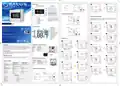
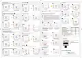
SALUS DT500 Thermostat User Guide


AC 230V
9
10
Button functions
DT500 / DT500RF Thermostat
DTRX5 Receiver
DT500RF
3V
DTRX5
COM
NO
MAX
16(5)A
1
2
5
6
2
X
AA
DT500, DT500RF
Press OK to confirm.
Thermostat will return to the main screen.
3
4
7
8
9
10
DT500 Thermostat Wiring Diagram
AC 230V
Programming - automatic mode
1. Boost function
9. When in manual mode, ON will turn the boiler on
When in manual mode, OFF will turn the boiler off
10. Receiver operates in automatic mode according to
the thermostat/Receiver output is controlled by the
On/Off slide switch.
DT500
3V
In this mode, user can set the schedules for thermostat (temperature setpoints for specific periods of time). To do this, firstly
choose programming mode: “5-2” (business days + weekend) or “24h” (each day separately) using parameter d04 from
Installer mode. Programmed schedules should use all time periods.
2. Manual Mode
NC
3. Frost protection
4. Schedule settings / Back button
5. Increase button
6. Decrease button
7. Confirm button
8. Holiday Mode
COM
NO
2
X
AA
1
2
Quick Guide
OR
LCD Icon Description
1
2
3
4
5
6
7
Day of the week
Program number
Program indicator
Temperature measured / set
Boost function
Low battery status
Wireless connection with the
receiver (only for DT500RF)
Heating Mode On
AC 230V
SALUS Controls
Units 8-10, Northfield Business Park
Forge Way, Parkgate,
Rotherham, S60 1SD
14
13 12 11
DT500
3V
10
9
NC
Press the button
to start programming.
Use the
or
button to select
Email: sales@salus-tech.com
1
day/days from which you want to start
programming.
MAX
5(3)A
COM
NO
2
X
AA
8
3
4
7
6
8
9
Frost Protection Mode On
10 Holiday Mode On
11 Manual Mode On
12 Temperature unit
13 AM / PM
2
SALUS Controls is a member of the Computime Group.
Maintaining
specification, design and materials of products listed in this brochure without prior notice.
a
policy of continuous product development SALUS Controls plc reserve the right to change
3
4
5
Setting the time
14 Clock
Issue Date: May 2022
V04
1
2
3 sec
Press OK to confirm.
Use the
the hour to start the program #1.
or
button to set
5
6
DT500 Thermostat Terminals description
Introduction
3 sec
DT500/DT500RF is a programmable room thermostat used to control room temperature. Device launching heating system by
shorting terminal blocks, simultaneously informing the action and showing this information on the LCD display. Extended
features allows us to use various operating modes - automatic (time schedules), manual, frost protection or holiday. Before use
please read this manual carefully. Use only AA 1.5 V alkaline batteries in the thermostat.. Place the batteries into the battery
slot located under the cover (see the Battery replacement chapter on the back). Do not use rechargeable batteries.
Terminal
Description
3 sec
COM
NO
Common Terminal
Switched Live ON
Switched Live OF
Press
,
simultaneously for 3 seconds.
and OK buttons
Press
or
to select the hour format.
NC
Product compliance
3
4
This product complies with the essential requirements and other relevant provisions of Directives EMC 2014/30/EU,
LVD 2014/35/EU, RED 2014/53/EU and RoHS 2011/65/EU. The full text of the EU Declaration of Conformity is available at the
Press OK to confirm.
Use the
the minutes to start the program #1.
or
button to set
Use terminals on
the backplate.
Safety Information
7
8
Use in accordance to national and EU regulations . Use the device as intended , keeping it in dry condition.Product for indoor
use only. Installation must be carried out by a qualified person in accordance to national and EU requlations.
DTRX5 Receiver Terminals description
Press OK to confirm.
Press
or
to set the hour.
Terminal
NO
Description
Technical specification
Switch Terminal
5
6
COM
Common Switch Terminal
Power Supply (230 V AC)
DT500 Thermostat
2 x AA alkaline batteries
5 (3) A
DT500RF Thermostat
Press OK to confirm.
Use the
the temperature for program #1.
or
button to set
L, N
Thermostat supply
Thermostat rating max
Outputs
2 x AA alkaline batteries
-
Voltage free NC / NO / COM terminals
5 °C – 35 °C
-
9
10
Temperature range
Temperature accuracy
5 °C – 35 °C
0.1 °C or 0.5 °C
DT500RF Thermostat Wiring Diagram
0.1 °C or 0.5 °C
Press OK to confirm.
Press
or
to set the minutes.
ITLC
SPAN 0.25 °C or 0.5 °C
ITLC
SPAN 0.25 °C or 0.5 °C
Control algorithm
Radio frequency
Dimension [mm]
-
868 MHz
AC 230V
120 x 90 x 29
120 x 90 x 29
7
8
Press OK to confirm.
Follow steps 4-9,
to define programs 2-6.
Press OK button to end programming.
DT500RF
3V
DTRX5 Receiver
230 V AC
DTRX5
Receiver supply
Receiver rating max
Outputs
COM
NO
2
X
AA
16 (5) A
Voltage free NC / NO / COM terminals
Radio frequency
Dimension [mm]
868 MHz
Press OK to confirm.
Press
or
to set day of the week.
98 x 98 x 25.2


| General | Details |
|---|---|
| Name | SALUS DT500 Thermostat User Guide |
| Make | SALUS |
| Language | English |
| Filetype | PDF (Download) |
| File size | 1.76 MB |
 (1 votes, average: 5.00 out of 5)
 Loading...

SALUS IT800 WIFI Smart Thermostat Installation Guide

SALUS 091FLRF Wireless Room Thermostat User Guide

SALUS Thermostat Sensor TS600 User Guide

SALUS Thermostat and Smart Plug Installation Guide

SALUS Programmable Wired Thermostat VS30W/VS30B Installation Guide

SALUS Wired Thermostat Installation Guide

SALUS Wired Digital Thermostat – Non-programmable HTRS230 User Manual

SALUS RT520 Radiator Thermostat User Guide

SALUS RT310 Thermostat User Manual

SALUS Thermostat RT520 User Manual

Salus DT500 Manual: Questions and Answers
Salus DT500 specifications
| Power supply | 2 x AA alkaline batteries |
| Setpoint range | 5 °C – 35 °C |
| Accuracy | 0.1 °C or 0.5 °C |
| Radio frequency | 868 MHz |
Can the Salus DT500 control a boiler in manual mode?
Yes. In manual mode, pressing ON turns the boiler on and pressing OFF turns it off. User Guide, p. 1
What is the difference between automatic and manual mode on the Salus DT500?
Automatic mode uses programmed temperature schedules. Manual mode lets you directly control the boiler on or off. User Guide, p. 1
Salus DT500 compared with other Salus thermostats
| Specification | Salus DT500 | Salus RT310RF Central | Salus WQ610RF Slim |
|---|---|---|---|
| Power supply | 2 x AA alkaline batteries | 230Vac 50Hz | 230V AC |
| Setpoint range | 5 °C – 35 °C | 5 ºC to 17 ºC | 5°C – 35°C |
| Radio frequency | 868 MHz | 868MHz | 2.4 GHz |
More Salus thermostat manuals

EUROSTER 2006TXRX Wireless Programmable Thermostat Installation Guide

aube technologies TH104PLUS Programmable Thermostat Owner’s Manual

Danfoss TP7000 Range Electronic 7 Day Programmable Room Thermostat Installation Guide

EAE TECHNOLOGY KNX ORIA Thermostat Installation Guide

GENERAL SENNA 270S Smart Room Thermostat User Manual

ENGO E20i Series Wi-Fi Wireless Internet Thermostat User Guide
Honeywell Home RTH Series T5 Smart Thermostat Installation Guide

WHITE-RODGERS 1F91-71 Multi Stage Electronic Digital Thermostat Installation Guide

beok TDR89 Wi-Fi Thermostat User Guide

SmartDHOME 01335-1864-00 Zone Thermostat for 2-Pipe Fan Coil with 0-10 VDC Fan Regulator and Valve Management User Manual