Home > Vaillant > Vaillant VRC 700 Weather Compensating Thermostat Instruction Manual

Vaillant VRC 700 Weather Compensating Thermostat Instruction Manual

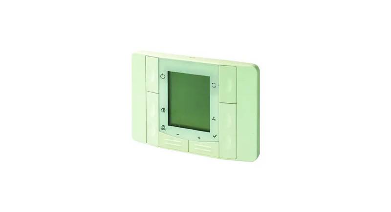
Remote control unit  
VR 91  
en Operating and installation  
instructions  
GeneralDetails
NameVaillant VRC 700 Weather Compensating Thermostat Instruction Manual
MakeVaillant
LanguageEnglish
FiletypePDF (Download)
File size0.24 MB
Download PDF
1 Star2 Stars3 Stars4 Stars5 Stars (1 votes, average: 5.00 out of 5)
Loading...
Vaillant VRT15 Room Thermostat User Guide
Vaillant VRC 700 Programmable Weather Compensating Thermostat Owner’s Manual
vaillant VR 92f/3 Wireless Additional Room Thermostat Instructions
Vaillant VRT 51f sensoROOM Wireless Room Thermostat Instruction Manual
Vaillant senso Comfort Thermostat Instructions

Vaillant VRC 700 Weather Compensating Thermostat Instruction Manual
Get the free PDF manual for the Vaillant VRC 700 Weather Compensating Thermostat Instruction Manual and access setup steps, usage instructions, and troubleshooting tips. 👉 View online or download now to keep your thermostat running smoothly!

Vaillant VRC 700 Weather Compensating Thermostat Instruction Manual Overview

Summary of Contents

  • Page 1: Remote control unit Operating and installation instructions
  • Page 2: Operating and installation instructions Safety For the end user General safety information for the end user Regulations (directives, laws, standards) Product description Operation Maintenance message Fault message Troubleshooting For the competent person
  • Page 3: Caution. Improper use of any kind is prohibited. If you cannot ensure the operation, have a competent person drain the heating installation. The product enables a zone to be controlled remotely via an eBUS interface. The following work must only be carried out by competent persons who are sufficiently qualified to do so: set-up, dismantling, installation, start-up, inspection and maintenance, repair, and decommissioning. Proceed in accordance with current technology. Do not install the product in rooms prone to frost. Intended use also covers installation in accordance with the IP code. Any other use that is not specified in these instructions shall be considered improper use. Inappropriate or improper use may cause damage to the product and other property. Compliance with all inspection and maintenance conditions listed in the instructions is required.
  • Page 4: Observe the national regulations, standards, directives, ordinances, and laws.
  • Page 5: System control can be read on the display. Always observe all operating instructions enclosed with the installation components. Ensure that room air can circulate freely around the system control. Store these instructions and all other applicable documents for further use. These instructions apply only to VR 91. The data plate is located inside the product and is not accessible from the outside. The CE marking shows that the products comply with the basic requirements of the applicable directives. You can only operate the remote control unit in combination with the VRC 700 system control. The product sends data, such as the current room temperature, to the system control. The operating instructions for the system control will provide you with information on the operating structure.
  • Page 6: Information on the operating concept with examples. A detailed description of the operating and display functions that the remote control unit also has. If you want to replace or remove the product, you must decommission the heating installation. This work should be carried out by a competent person. If maintenance is required, the text Maintenance and the symbol appear in the remote control unit display. We only grant a Vaillant manufacturers warranty if a suitably qualified engineer has installed the system in accordance with Vaillant instructions. If a fault occurs in the heating installation, a fault message will appear in the display. The competent person must clear or rectify the fault in the heating installation. Clean the casing with a damp cloth and a little solvent-free soap. Always observe all the operating and installation instructions included with the system components.
  • Page 7: Minimum cross-section: ≥ 0.75 mm² Maximum line length: ≤ 125 m The data plate is located on the product's PCB and cannot be accessed from the outside once the product has been mounted on the wall. Mount the remote control unit on an interior wall of the main living room in a position that ensures accurate measurement of the room temperature. The data plate contains information such as installation height, serial number for identification, product designation, rated voltage, and rated current. The CE marking shows that the products comply with the basic requirements of the applicable directives as stated on the declaration of conformity. The declaration of conformity can be viewed at the manufacturer's site. Connect the eBUS line. Use standard commercial lines for the wiring. Check the scope of delivery, which includes the remote control unit, fastening material, and documentation. Screw in the wall base in accordance with the figure.
  • Page 8: Start-up When you are operating the heating installation for the first time after installing the electrical wiring, the installation assistants for the system components and the remote control unit start automatically. All settings that you have applied using the installation assistant can be changed again at a later date via the level for the end user and competent persons. Configuring the settings on the remote control Select the required language in the Language function. Enter the address the system control needs in order to communicate with the remote control unit in the Remote control address function. Electrical installation Only qualified electricians may carry out the electrical installation. When connecting the eBUS line, there is no need to pay attention to the polarity. If you would also like to use the room temperature sensor in the remote control unit, select the Temp. mod. or Thermost. setting in the Room temp. mod. function. Changing the settings later All settings that you have made via the installation assistant can be changed again at a later date via the end user or installer level.
  • Page 9: Handing over to the end user Inform the end user of how to handle and operate their product. Provide the end user with all relevant instructions and unit documentation for safe-keeping. Go through the operating instructions with the end user. In particular, draw the end user's attention to the safety warnings that they must follow. Inform the end user that room air must be able to circulate freely around the product. You can use this function to reset all the set values that you configured using the remote control installation assistant. The remote control has an end user level and an installer level. You can only operate the remote control unit in combination with the VRC 700 system control. A detailed description of the operating and display functions that the remote control unit also has. This function allows you to read the status of the heating installation.
  • Page 10: Ensure that there is no personal data on or in the product before disposal. Customer service addresses can be found in the installation instructions for the system control. Rated voltage for the remote control unit is 9 to 24 V. Rated surge voltage is 330 V. Rated current is less than 50 mA. Supply line cross-section ranges from 0.75 to 1.5 mm². The IP rating is IP 20. Protection class is III. Maximum permitted environmental temperature is from 0 to 60 °C. Current room air humidity is between 20 to 95 %.
  • Page 11: Appendix Operating modes Heating: off, Auto, Day, Set-back Cooling: off, Auto, Day Advanced functions: 1 day at home, 1 day away from home, ventilation boost, party function A detailed description of the functions can be found in the operating instructions for the system control. Information on system status and fault status. Current values for room air humidity and dew point. Day temperature settings for heating and cooling. Contact details for the installer. Serial number and unit number information.
  • Page 12: Setting level values include minimum, maximum, and default settings. Time programmes for heating and cooling can be set for individual days and blocks. Specific time periods can be defined for each day of the week. Days away from home scheduling allows users to set start and end dates. Days at home scheduling also requires start and end dates. Basic settings include language selection, display contrast, and button lock options. Preferred display can be set to heating or cooling. Room temperature offset can be adjusted within a specified range. Operating and installation instructions are provided for user reference.
  • Page 13: Setting level Basic settings Enter zone name Installer level Enter code A.3 Troubleshooting Symptom Possible cause Software error For the competent person
  • Page 14: Installer level settings include entering a code between 000 and 999. The system configuration displays fault status and current values. If no fault is present, the status will indicate No fault. Room temperature sensor faults may indicate a defective sensor or no zone assignment for the remote control. To remedy a room temperature sensor fault, replace the remote control or set the correct address on the remote control unit. System faults may arise from issues in the heating installation, requiring assessment of fault messages. A dark display may indicate a software error or a lack of power supply to the heat generator. If the display remains unresponsive when the rotary knob is turned, it may also indicate a software error or a defective product. No changes in the display when selection buttons are pressed can suggest a software error or product defect. Operating and installation instructions are provided for proper usage and troubleshooting.
  • Page 15: Symptom: Lines appear instead of set and read-out values. Possible cause: Communication fault. Measure: Check the plug connection. Measure: Replace the cable. Operating and installation instructions.
  • Page 16: Supplier: Vaillant Ltd. Publisher/manufacturer: Vaillant GmbH These instructions, or parts thereof, are protected by copyright and may be reproduced or distributed only with the manufacturer's written consent. Subject to technical modifications.