DAIKIN IM 1366 Remote Integrated Thermostat Instruction Manual


Installation and Maintenance Manual IM 1366
Group: Applied Terminal Systems
Part Number: IM1366
Date: June 2023
Remote Integrated Thermostat
Contents
Overview . . . . . . . . . . . . . . . . . . . . . . . . . . . . . . . . . . . . 2
Mounting Considerations . . . . . . . . . . . . . . . . . . . . . . 2
Terminations . . . . . . . . . . . . . . . . . . . . . . . . . . . . . . . . 3
Initial Start-up and Display Descriptions . . . . . . . . . . 4
Occupancy Indicator . . . . . . . . . . . . . . . . . . . . . . . . . . 5
Fan Status & Speed Indicators . . . . . . . . . . . . . . . . . . 5
System Mode Selection . . . . . . . . . . . . . . . . . . . . . . . 5
View and Clear Alarms . . . . . . . . . . . . . . . . . . . . . . . . 5
7-Day Schedule Setup . . . . . . . . . . . . . . . . . . . . . . . . 6
Specifications . . . . . . . . . . . . . . . . . . . . . . . . . . . . . . . . 7
©2023 Daikin Applied, Minneapolis, MN. All rights reserved throughout the world.This document contains the most current product information as
of this printing. Daikin Applied Americas Inc. has the right to change the information, design, and construction of the product represented within the
™® MicroTech and Daikin Applied are trademarks or registered trademarks of Daikin Applied Americas Inc. The following are trademarks or
registered trademarks of their respective companies: BACnet from American Society of Heating, Refrigerating and Air-Conditioning Engineers, Inc.;
Echelon, LonWorks, LonMark, and LonTalk from Echelon Corporation; Modbus from Schneider Electric; and Windows from Microsoft Corporation.

| General | Details |
|---|---|
| Name | DAIKIN IM 1366 Remote Integrated Thermostat Instruction Manual |
| Make | Daikin |
| Language | English |
| Filetype | PDF (Download) |
| File size | 0.28 MB |

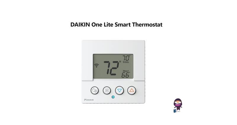
DAIKIN One Lite Smart Thermostat User Guide

Daikin One Lite Smart Thermostat Instruction Manual

DAIKIN DTST-ONE-ADA-A One Touch Smart Thermostat Installation Guide

DAIKIN IM 1368 Vertical Stack WSHP Thermostat Instruction Manual
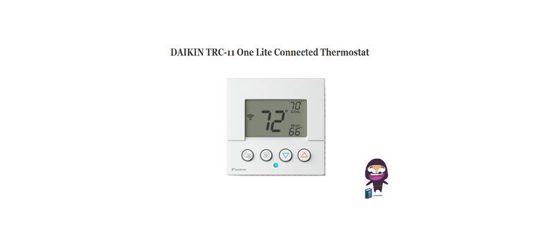
DAIKIN TRC-11 One Lite Connected Thermostat Instruction Manual
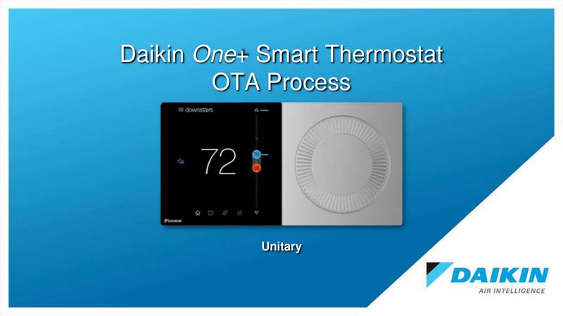
DAIKIN ONE Smart Thermostat Instructions

DAIKIN DKN509 Wireless Communicating Thermostat Instruction Manual
DAIKIN SQNSQ22 One Touch Smart Thermostat User Manual
EMSQ22 Daikin ONE Lite Smart Thermostat User Manual

DAIKIN S21 One Lite Smart Thermostat User Guide
DAIKIN IM 1366 Remote Integrated Thermostat Instruction Manual Overview
Summary of Contents
- Page 1: Installation and maintenance manual for the remote integrated thermostat. Overview of the document contents. Mounting considerations for installation. Details on terminations. Initial start-up and display descriptions. Occupancy indicator functionality. Fan status and speed indicators. System mode selection process. Instructions to view and clear alarms. 7-day schedule setup information. Specifications of the product.
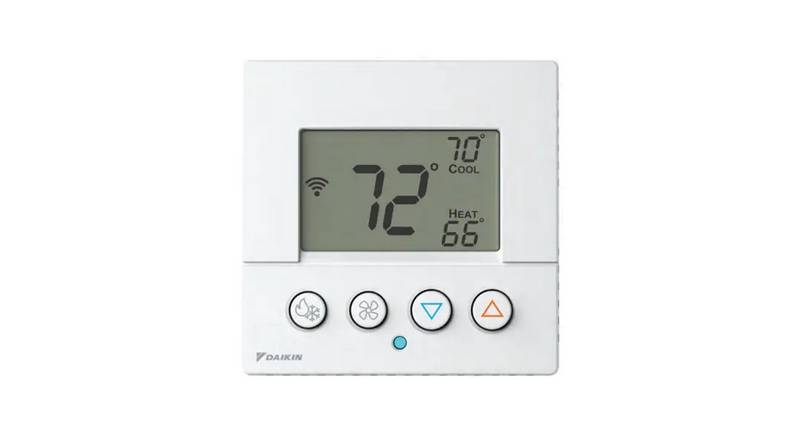
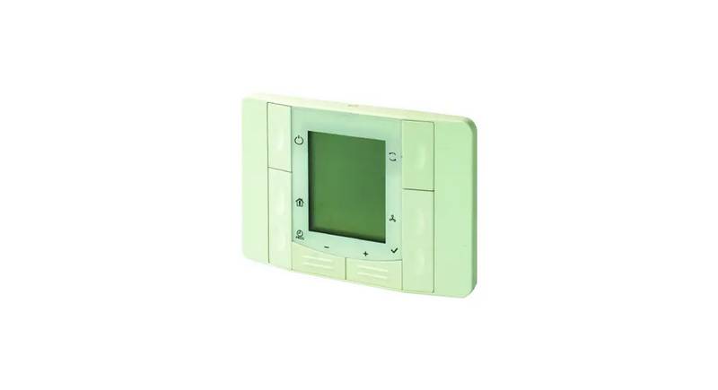
- Page 2: Mounting considerations: The remote integrated thermostat is used in conjunction with MicroTech 4 Lite equipped units. The thermostat has a digital display for temperature, occupancy, fan speed, system mode, alarm, setpoint, and status indication. The device is suitable for semi-flush mounting with a recessed conduit box. The unit should not be mounted in recesses, shelving, behind curtains or doors, or above or near direct heat sources. Avoid direct sun and draught. The conduit must be sealed on the device side, as currents of air in the conduit can affect the sensor reading. Local installation regulations must be observed. Use a flathead screwdriver to gently pry the front covering to access the terminals. Wipe the display as needed with a damp water-only cotton cloth. Do not use any type of cleaner as it may damage the buttons or scratch the display. Do not paint.
- Page 3: Terminations Daikin Applied recommends using a twisted shielded pair of at least 22AWG for the power wire connections. The shield should be earth grounded only at the power source. Larger gauge wire may be required for long runs. All wiring must comply with the National Electric Code (NEC) and local codes. Do NOT run any of this device’s wiring in the same conduit as other AC power wiring. Tests show that fluctuating and inaccurate signal levels are possible when AC power wiring is present in the same conduit as the signal lines. The thermostat has a 2-wire interface for data and power supply. Device power supply, data (positive) Device power supply, data (negative)
- Page 4: Thermostat display icons include temperature area, time, fan speed, and mode indicators. Initial start-up may take up to 5 minutes for the thermostat to establish communication with the controller. The thermostat status cycle displays the current measured room sensor temperature and the active setpoint, switching every 5 seconds. Temporary setpoint adjustment is done using the minus (-) and plus (+) buttons, requiring effective occupancy to be set to occupied or bypass. Temporary setpoint adjustment will not function in program mode or if occupancy is set to standby or unoccupied. Pressing the OK button confirms the setpoint change, while failure to do so within 10 seconds will discard the change. Subsequent presses of the adjustment buttons will increment the setpoint value by 0.5 degrees. The display will show STPT when adjusting the active setpoint value. The thermostat can indicate various modes such as auto, economy, comfort, cooling, heating, and dehumidification. Alarm and service mode indicators are also part of the display features.
- Page 5: Occupancy Indicator When the Effective Occupancy is set to OCCUPIED or BYPASS, then the Comfort Mode Active icon will display. Mode Indicators The status bar indicates fan speed, which can be adjusted only on units configured for constant air volume control. COOL This icon is active only when the unit is in cooling, economizer, or dehumidification modes. DRY This icon is active only when the unit is in dehumidification mode. HEAT This icon is active only when the unit is in heat mode. AUTO This icon is active only when the unit is in auto mode. View and Clear Alarms When there is an active alarm, the alarm icon will blink every second. System Mode Selection The MODE button allows the user to select Auto, Cool, Heat, or Fan Only modes of operation. Auto Mode The unit switches automatically to provide heating, cooling, or dehumidification. Fan Only Mode The unit will operate the fan at the selected fan speed setting.
- Page 6: The device will prompt the user to select the unoccupied cooling setpoint. Pressing the plus (+) or minus (-) buttons will increment and decrement the unoccupied heating setpoint value. The user can exit the 7-Day Schedule Setup at any time by pressing the PROG button. Hold the PROG button for more than 10 seconds to enter the Occupancy Scheduler State. The device will exit 7-Day Schedule Setup automatically if no operation was performed for 60 seconds. Pressing the plus (+) or minus (-) will cycle through the days of the week. Press the PROG button to enter time and date settings. The first variable is time setting, allowing changes to hour, minute, time format, and calendar. Pressing the plus (+) or minus (-) buttons will cycle the date. Pressing and holding the Presence and Mode buttons for at least 3 seconds will clear the active alarm.
- Page 7: Specifications Supply voltage: DC 21-30 V, MAX. 0.31 VA Operating data: Measuring range 0-40 °C, thermal time constant (sensor) approx. 15 seconds, measuring accuracy (5-30 °C) ±1.0 K Display: Segment LCD, setpoint adjustment, operating mode, manually selected fan speed, control sequence Time display: Time and weekday setting, parameter setting (only when selected) Interfaces: 2-wire interface KNX, 9.6 kbps Housing protection: IP 30 Ambient conditions: Normal operation transport, temperature 5-40 °C, humidity <85% relative humidity Industry standards: UL916, UL873, CSA C22.2M205
- Page 8: Daikin Applied Training and Development emphasizes the importance of caring for modern, efficient equipment. For training information on Daikin Applied HVAC products, visit the website or contact the Training Department. All equipment is sold under standard terms and conditions, including a Limited Product Warranty. Consult a local Daikin Applied Representative for warranty details. Aftermarket services are available through local parts and service offices. The document contains the most current product information as of printing. For the latest updates, visit the website. Products are manufactured in an ISO Certified Facility.

Wiser CCTFR6100 Radiator Thermostat Instruction Manual

SALUS RT310RF Digital Wireless Central Heating Room Thermostat User Manual

GENERAL ARUNA FH25S Underfloor Heating Thermostat User Manual

SMART TEMP SMT-131 Hotel Touchscreen Thermostat User Manual

MClimate MC-LW-V02 Smart Radiator Thermostat User Manual

STELPRO STZW402 – KI Electronic Thermostat Owner’s Manual

Honeywell RTH6300B Programmable Thermostat Installation Guide

Google Nest Learning Thermostat (4th gen) Installation Guide

UNILUX TA640FCW-ULX HVAC Thermostat User Manual

beok TDR89 Wi-Fi Thermostat User Guide