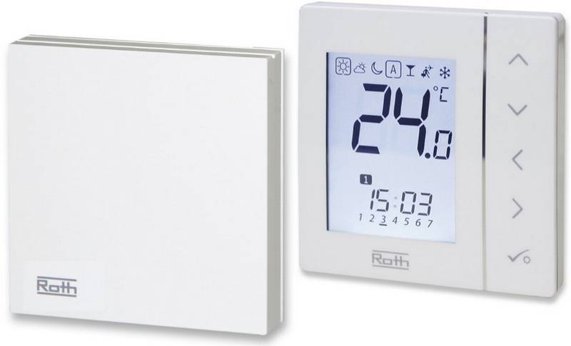
Roth Basicline Room Thermostat Instructions


Room thermostat Basicline H/C 230 V
manual
1. General notes
>
>
To avoid interference, the sensor wire should not be laid together with other
conducting wires.
Read these instructions carefully before installation and commissioning to ensure
correct use! The unit may only be operated in the manner described. Any use under
other conditions is not permitted and excludes liability for any resulting damage.
If the external sensor is used as floor sensor, it must be installed in a conduit.
If an open conduit is used, this must be closed with plugs to prevent any tile
cement or screed from entering the conduit.
The appliance may only be operated with the accessories recommended in this
manual.
5.2 Cooling lock function
The unit may only be cleaned when closed with a dry cloth.
The slide switch S2 in the device allows the
selection whether the cooling mode is
deactivated.
Cooling activated
Cooling deactivated
2. Meaning of the symbols
1
0
1
0
Safety instructions are highlighted by a warning triangle and, depending on the
degree of danger, are displayed as follows.
S2
S2
The default factory setting is activated cooling
mode (switch position is at “0” as shown in
the opposite drawing).
Attention!
General danger zone. Death, serious bodily injury or considerable damage to
property can occur if appropriate precautions are not taken!
5.3 Changeover of the internal/external tem-
perature sensor
Danger from electric current
The slide switch S1 in the device allows the
selection of the internal or external
temperature sensor to measure the room
temperature.
Warning of dangerous voltage or current.
3. Application
The electronic Basic H/C 230 V room thermostat for the room temperature-
dependent regulating of heating and cooling equipment is designed for use in dry
closed areas.
The internal temperature sensor is active as
default factory setting (switch at the position
shown in the opposite drawing).
4. Function
If the temperature is to be measured with the
external sensor
The internal or external temperature sensor
measures the room temperature. The rotary
RFK 133/4 (Mat.-Nr. 1135006690) or
button
temperature
range 5 °C to 30 °C (scale-digits 1-6).
The internal light-emitting diodes
the heating / cooling is switched on.
is used to set the desired room
RFW 103 (Mat.-Nr. 1135006689) (please
order separately), then the slide switch must
be moved to the right. The external sensor
must be connected to terminals 7 and 8 (as
shown in the connection diagram).
S1
S1
to value within the
a
internal sensor
external sensor
indicate that
An input (c/o signal) allows the change to cooling
mode by connecting L-potential (230 V).
6. Connection diagram
An energy saving input allows the setpoint to be
lowered (heating mode) or increased (cooling
230 V
PE N L
heating/cooling
switching
Basicline
H/C 230 V
mode) using
thermostat) or an external clock.
a
suitable control device (clock
1
2
3
4
5
6
7
8
C/O
L`
4.1 Heating
actuator
Option
L
The output is triggered when the room temperature falls below the set setpoint,
indicated by a red LED. The active lowering reduces the setpoint by approximately 2 K.
N
N
4.2 Cooling
The output is triggered when the room temperature rises above the setpoint,
indicatedbyablueLED. Theactiveincreasingrisesthesetpointbyapproximately 2 K.
5. Installation — only by authorized trained personnel
Only authorized trained personnel may make the connection and perform
service!
Option:
ext. temperature sensor
Connection errors can cause damage to the automatic control device!
No responsibility will be taken for any damage resulting from the incorrect
connection and/or improper use!
7. Technical data
Theconnectionof the controlunitrequiresthatanallpoleswitch/circuitbreaker
is available in the building installation.
Type:
Basicline H/C 230 V
Operating voltage:
Desired temperature setting:
Temperature range:
Sensor tolerance:
230 V AC / 50 Hz (±10 %)
exterior rotary button
+5 to +30 °C
It must be marked as a disconnecting device for the unit. This switch must be
suitably located and easily accessible to the user.
Before working on the unit, switch off all poles of the cables.
±1 K
Switching difference:
Sensor:
Output:
±0.2 K fixed
internal or external (optional)
triac output with potential
0.8 A, 230 V AC
(resistive / max. 5 Roth actuators)
lowering / increasing by approx. 2K
screwless terminals
1.C (no limiter method of operation)
2.5 kV
>
>
The device is designed only for connection to permanent wiring in dry closed
areas.
Maximum permitted switching current:
The automatic control device must be installed so that it measures the average
room temperature, avoid the vicinity of inlet and outlet channels, windows and
doors. Install on interior walls approximately 1.3 to 1.5 m above the floor, avoid
direct sunshine.
Energy saving input
Electrical connections:
Method of operation:
Impulse withstand voltage:
Pollution degree:
>
The VDE 0100 and the regulations of the local power utility company must be
observed.
2
Perm. ambient temperature:
max. rel. humidity
max. operating height
Housing:
0 to +40 °C
85% rH
>
>
>
Devices with safety extra-low voltage (SELV) must not be connected.
The connection must be made using the accompanying block diagram.
up to 3000m above sea level
Material upper part ABS/PC
(impact- resistant, flame-protected)
lower part: PA6 GF30
81 x 81 x 16 (25) mm
with flush-mounting box
through flush-mounting box
IP 30
The same phase (L) must be used for the power supply (terminal 3), the c/o-
signal (terminal 1) and the lowering increasing (terminal 6).
If the device does not function, first check the correct connection and the power
supply.
Dimensions:
Mounting:
Cable routing:
Degree of protection:
Safety class:
Weight:
5.1 External Sensor (optional)
Only RFK 133/4 or RFW 103 sensors may be used.
II
The sensor wire is live wire. Double insulation / dielectric strength
approx. 90 g
up to 3 kV must therefore be used! The installation notes are to be observed.
8. RETURN AND DISPOSAL OF ELECTRICAL
AND ELECTRONIC APPLIANCES
Old appliances that are labelled with the "crossed-out wheelie bin" symbol
must not be disposed of with household waste, but must be disposed of
separately.
Subject to change without prior notice
| General | Details |
|---|---|
| Name | Roth Basicline Room Thermostat Instructions |
| Make | Roth |
| Language | English |
| Filetype | PDF (Download) |
| File size | 0.17 MB |


Roth Basicline 230T Programmable Clock Thermostat Instruction Manual

Roth Basicline H 230V Room Thermostat Instructions

Roth Minishunt Room Thermostat Installation Guide

Roth Touchline SL Standard Room Thermostat Installation Guide

Roth Minishunt Plus Wireless Room Thermostat Installation Guide

Roth VVS-nr. 466397.058 Softline Standard Room Thermostat Instruction Manual

Roth SL Car Air Conditioner Thermostat Instructions

Roth Minishunt Plus Thermostat and Capillary Sensor Installation Guide

Roth Touchline SL Plus Room Thermostat Instruction Manual
Roth Basicline Wired Thermostat Installation Guide


Digital Touch Thermostat Troubleshooting User Guide

ENSTO ECO10BTW-J Heat Control Thermostat Instruction Manual

GENERAL LIFE 260S Digital Room Thermostat User Manual

HITACHI ATW-RTU-05 Wireless Intelligent Room Thermostat Instruction Manual

Danfoss RT 103 Thermostat Installation Guide

Vaillant VRT 51f sensoROOM Wireless Room Thermostat Instruction Manual

THE HEATING COMPANY Slim and Compact WiFi Thermostat User Manual

Danfoss VIMCA20F 24V RT Room Thermostat Installation Guide
beok-controls TGR86 Wi-Fi Thermostat User Guide

vtech Installing E-Smart W960 Thermostat User Manual