Amana DS01G Digi Smart Thermostat Instruction Manual


PTAC
WIRELESS KITS (DT01*, DS01G, DD01E, DD01F)
INSTALLATION INSTRUCTIONS
FAN
MODE
DD01E
DS01G
DT01A
DT01G
DD01F
The following installation instructions are for a typical installation.
Please contact your PTAC salesperson
for additional assistance and explanation prior to ordering materials or cutting openings.
ATTENTION INSTALLING PERSONNEL
As a professional installer you have an obligation to know the product better than the customer.
This includes all safety precautions and related items.
Prior to actual installation, thoroughly familiarize yourself with this Instruction Manual.
Pay special attention to all safety warnings. Often during installation or repair
it is possible to place yourself in a position which is more hazardous than when the unit is in operation.
Remember, it is your responsibility to install the product safely and to know it well enough
to be able to instruct a customer in its safe use.
Safety is a matter of common sense...a matter of thinking before acting.
Most dealers have a list of specific good safety practices...follow them.
The precautions listed in this Installation Manual are intended as supplemental to existing practices.
However, if there is a direct conflict between existing practices and the content of this manual,
the precautions listed here take precedence.
is a registered trademark of Maytag Corporation or its related companies
and is used under license to Goodman Company, L.P., Houston, TX. All rights reserved.
Goodman Company, L.P.
5151 San Felipe, Suite 500 ꢀ Houston, TX 77056
www.amana-ptac.com ꢀ © 2009-2011, 2013-2018 Goodman Company, L.P.
10/2018
IO-729E
Due to policy of continued product improvement, the right is reserved to change specifications and design without notice.

| General | Details |
|---|---|
| Name | Amana DS01G Digi Smart Thermostat Instruction Manual |
| Make | Amana |
| Language | English |
| Filetype | PDF (Download) |
| File size | 0.66 MB |


Amana MMW-2 Horizontal Digital Wireless non EMS Wall Thermostat Instruction Manual

Amana ATST-CWE-BL-A Smart Thermostat Owner’s Manual

Amana DS01 PTAC Wireless Thermostat User Manual

Amana DS01G Digi Smart Thermostat Instruction Manual Overview
Summary of Contents
- Page 1: Wireless kits installation instructions are provided for a typical installation. Contact your PTAC salesperson for additional assistance prior to ordering materials or cutting openings. As a professional installer, you must know the product better than the customer, including all safety precautions. Familiarize yourself thoroughly with this instruction manual before installation. Pay special attention to all safety warnings to avoid hazardous situations during installation or repair. It is your responsibility to install the product safely and instruct the customer in its safe use. Safety is a matter of common sense and thinking before acting. Follow specific good safety practices recommended by dealers. If there is a conflict between existing practices and this manual, the precautions in this manual take precedence. The content is protected and all rights are reserved by Goodman Company, L.P.
- Page 2: Before beginning installation, please read important notes. Devices must be powered with field-installed wiring run from the thermostat location to the unit location and from door sensor location to PTAC location. If using wireless platforms DP01* or DL01E, room numbers must be configured in the control board prior to binding wireless devices. All units must have DT01* antenna for wireless devices to communicate properly. The sequence of installation includes mounting peripherals, verifying operation of the door sensor, programming room numbers, binding peripherals, and reinstalling peripherals to their mounted backplates. Installation and videos are available on the website. A DT01* antenna must be installed on the digital PTAC for operation of the DS01* remote RF thermostat or DD01* combination PIR motion sensor and door switch. Disconnect power to the unit before installation. Restore power to the PTAC unit after installation. The LED must be oriented at the top of the antenna housing for proper unit operation.
- Page 3: Drill a 7/32” holes and tap plastic anchors into the wall. Screw mounting base plate to the wall. Do not snap thermostat into place until after binding process. A DT01* must be installed on the digital PTAC unit for the DS01* to be operable. Select thermostat mounting location about five feet above the floor, on an inside wall, out of direct sunlight. Install two AA batteries into the back of the thermostat. Do not install thermostat on wall plate until all configuration settings and binding processes have been completed. If the option for wired power is used, the two thermostat wires can be connected to the thermostat. Thermostat has motion sensing capability for energy management operation. If connecting a wired door switch to this thermostat, it can be connected to the thermostat.
- Page 4: Loosen set screws on wired terminals labeled REMOTE and insert wires into the openings. DD01E and DD01F must be mounted on the top door frame as close to the door as possible in the horizontal position. A DT01* must be installed in the PTAC unit for the DD01E or DD01F to be operable. Mount the back plate on the door trim directly above the door using the enclosed screws. Choose a location for mounting the back plate that will provide good coverage of the PIR for motion into the room. For battery powered, the 2 jumpers must be positioned on the center and left pins. For external power connection, the 2 jumpers must be positioned on the center and right pins. Install two batteries into the back of the sensor. Terminals are marked “+” and “-” for polarity. Do not put batteries into the device until after the magnet location is selected to test.
- Page 5: Power connection is essential for the door sensor installation. In cases without a top door frame, the sensor should be mounted on the wall next to the door. A wired magnet can be recessed or surface mounted and wired to the door sensor. The door sensor has four terminal locations for wired power and/or wired magnets. The two terminals closest to the binding button are for wired magnet connections. Run the magnet wires through the opening in the door sensor wall plate. Using a screwdriver, push down on the terminal button to open the socket for wire insertion. Connect the power wires from the door sensor to the PTAC unit on terminals C & R. For battery connection, ensure the jumper is placed correctly as indicated. For a 24v powered connection, the jumper must also be placed as shown.
- Page 6: Door magnet installation involves several key steps. The magnet buckets are shipped with the magnets in position A, which may change based on door alignment. Mount the door magnet holder close to the bottom of the motion sensor, ensuring it is no more than 1/8 from the bottom center when the door is closed. Select the correct slot in the magnet holder to achieve a distance of 15/16 from the back of the sensor mounting plate to the center of the magnet. Ensure the unit is properly placed vertically by checking if a business card can slide between the magnet and the sensor. Secure the magnet holder with the provided screws and verify that it does not interfere with the door's normal operation. Alignment guides on the bottom of the DD01E must be 15/16” from the sensor mounting plate. Do not install batteries until ready to test the magnet location with the DD01E.
- Page 7: Security screw location is on each side of the sensor. The magnet must be 15/16” from the sensor mounting plate. The magnet holder may extend above the door 1/8” max or the DD01E or DD01F may extend below the door frame. Ensure the magnet is no more than 1/8” from the bottom center of the sensor. The space from the top of the magnet holder and the bottom of the DD01E or DD01F door cannot be more than 1/8”. The ideal spacing allows a business card to be easily placed between the DD01E or DD01F sensor and the magnet holder. A straight edge screwdriver may be placed in slots for magnet removal. Install the magnet in the correct slot. Select one of the three slots that places the magnet 15/16” from the sensor mounting plate on the door frame. The door frame and door usually will not align.
- Page 8: Construction style 1 involves placing the magnet in Position A when the door and frame align. Construction style 2 requires placing the magnet in Position B when the door extends into the room beyond the door frame. Construction style 3 specifies placing the magnet in Position C when the door extends into the room. Construction style 4 indicates placing the magnet in Position A when the door frame extends into the room beyond the door. Two 1/4” spacers are included in the kit for specific installation needs. The note mentions that spacers are provided for instances where the door is recessed behind the door trim. There is a line on the bottom of the DD01E and DD01F to assist in aligning the magnet in the proper bucket location. The graphics provided are for example only; always measure and place the magnet in the proper slot.
- Page 9: The alignment guide is at 15/16” from the back plate. The center of the magnet in the holder must be 15/16” from the sensor mounting plate. When properly installed, the center line mark on the bottom of the DD01E or DD01F will line up with the center of the magnet holder. Choose magnet position A, B, or C to align the magnet 15/16” from the back of the DD01E or DD01F. To verify that the door sensor is installed properly, install batteries into DD01E or DD01F and snap the sensor onto the wall plate. The green light in the lens should illuminate when the door is closed and turn off when the door is opened. The PTA control will automatically self-configure to work with the wall thermostat if installed and bound. The PTA control will activate pre-configured energy management routines when the DD01E or DD01F is installed and bound to the PTA. To enter configuration feature mode, press and hold the up and down arrow keys and quickly press the OFF key twice within a two-second time frame. Ensure that you are in the proper configuration setting before pressing the + or - key to avoid unintended changes.
- Page 10: The display will alternate between displaying the feature code and the option code 0 (factory default setting). Press the HEAT button one time to get into C1 mode and then the display will alternate between C1 and 0 - the factory default. If an RF DS01* has been bound to the unit the display will alternate between C1 and rE. The PTAC control can be set for a 4-digit room number. If wireless platform DP01* or DL01E are being utilized, then room numbers must be configured in the control board prior to binding wireless devices. Do not attempt to bind more than one room at a time at the same property. The wireless devices (DS01G and or DD01E) must be bound to the PTAC DT01* control for proper in-room communication. If you need to rebind one device, then you must rebind both devices during the same learn mode event. If a room contains more than one unit (a suite), a suffix must also be entered to identify which unit is in the main room and which unit(s) are in bedroom(s). Master unit always must have a 01 suffix and slaves a suffix of 02, 03, etc.
- Page 11: If the display does not show in 1-2 seconds, press and release the white button a second time. If both a DD01* and a DS01* are being bound, then the display will show a specific indication. Press “OFF” on the PTAC touchpad to exit the binding sequence. Slide the top of the thermostat down onto the mounting base plate and then snap into place. Provided optional security screw may be used in the lower center of the thermostat. Snap motion sensor onto motion sensor mounting plate. Provided optional security screws may be installed on the right and left side of the sensor. If you wish to change from the factory default settings, configure the device or devices that were bound. If a wireless device is replaced or added, all devices will need to be bound/re-bound to the unit.
- Page 12: Configuration settings chart outlines various configuration codes and their descriptions. Interface options include chassis membrane, wireless remote, and wired thermostat. Fan operation settings detail options for cyclic and continuous fan modes. Reverse cycle operation and heat pump configurations are specified. Room identification digits are categorized into multiple sets. Occupancy settings include wired or wireless options and automatic entry timing. Temperature limiting settings for both cooling and heating are provided. Sensorless unoccupied time and temperature settings for unoccupied periods are listed. Jace group codes range from 1 to 32 and include various decimal options. Room prefix and suffix codes are defined for additional configuration.
- Page 13: Setback temps - DD01E / DD01F The DD01* and the Digi Smart™ control can be programmed for 3 different times to activate temperature setbacks. The current factory default temperature setbacks in v2.5 software release are: 2º from set point in 30 minutes, 3º in one hour, and 6º in three hours. If a change to the factory default temperature settings is desired, use the following instructions. When first entering the configuration mode, if you see “ - - ” then you have version 2.5 or higher. To select first unoccupied set back temperature, press the HEAT key until the feature code comes up. The first unoccupied setback time is the time between when the control determines that the room is not occupied and when the control sets the operating set point temperature back. Press HEAT key to scroll to second unoccupied setback temperature. Press HEAT key to scroll to second unoccupied setback time. Press HEAT key to scroll to third unoccupied setback temperature.
- Page 14: Press the HEAT key to scroll to the third unoccupied setback time. Press either the up or down arrow to the desired third unoccupied setback time. To exit configuration mode, press the OFF key. Configuration feature mode will also automatically exit if no keys are pressed for a period of two minutes. The changes made in configuration mode are now in effect. Additional codes are present and may be accessed within this menu. Contact the manufacturer for additional information.
- Page 15: Suggested wireless thermostat locations in typical room layouts include selecting a mounting location about five feet above the floor, on an inside wall, out of direct sunlight, and away from sources of radiant heat. Ensure the location is out of the path of foot traffic to prevent accidental damage to the thermostat. Due to the motion sensor inside the thermostat, do not point it towards a window. This equipment has been tested and complies with the limits for a Class B digital device, pursuant to Part 15 of the FCC Rules. The equipment generates, uses, and can radiate radio frequency energy, which may cause harmful interference if not installed according to the instructions. If interference occurs, users are encouraged to try various measures to correct it. The equipment must be installed in accordance with the instructions provided in this document to maintain authority to operate it. This equipment contains no user serviceable parts, and modifications without consent could void the user's authority to operate it. To comply with FCC RF exposure requirements, a minimum separation distance of 20cm (8 inches) is required between the equipment and all persons.
- Page 16: is a registered trademark of Maytag Corporation or its related companies and is used under license to Goodman Company, L.P., Houston, TX. All rights reserved. Due to our policy of continued product improvement, the right is reserved to change specifications and design without notice.
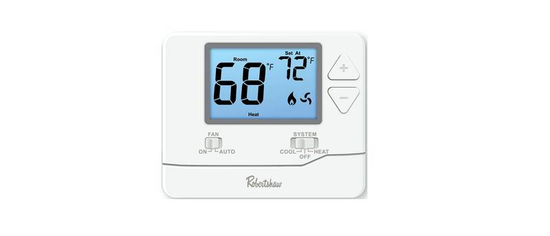
Robertshaw RS8210 Thermostat Installation Guide

ROMA HEATING CT1000 WiFi Colour Touch Screen Thermostat User Manual

Gigaset ONE X Thermostat User Guide

EMOS P5611OT Wireless Thermostat Instruction Manual

sensi ST765470 Thermostat Installation Guide

degrii THM Edge Cutting Smart Thermostat User Guide

GENERAL LIFE HT220 RF Wireless Room Thermostat User Manual

Honeywell TH8321WF02 Vision Pro WiFi Programmable Thermostat User Manual

BEOK BOT-R6X Wireless Gas Boiler Thermostat User Manual

emos P5616OT Wireless Thermostat Instruction Manual