
SKYTECH 5320P Programmable Thermostat Fireplace Remote Control Instruction Manual


INSTALLATION
Protection from extreme heat is very important. The remote receiver should be kept away from temperatures exceeding
130ºF. Extreme heat can cause damage, which is not covered under warranty.
•
Before installation, make sure you turn the slide switch to OFF. After installation, make sure you turn the slide switch
to REMOTE.
•
•
The remote receiver can be placed on the replace hearth or under the replace behind the control access panel.
Use the wires attached to the remote receiver to connect to the gas valve or the electric module (piggyback
connectors have both male & emale terminals or fexibility).
•
Be sure that the connectors do not touch each other or other bare metal surfaces; this will cause the appliance to turn
ON. The connectors may be wrapped with electrical tape to prevent this.
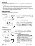
WIRING INSTRUCTIONS
A qualied electrician should install the remote control system.
MILLIVOLT VALVES
•
Connect one wire from the remote receiver to the TH terminal
on the gas valve.
TERMINAL BLOCK
ON MILLIVOLT
GAS VALVES
TH
TP
TP
TH
•
Connect the other wire from the remote receiver to the TH/TP
terminal on the gas valve.
THERMOPILE/
PILOT LIGHT
MILLIVOLT SYSTEM CHECK
•
Ensure that the pilot fame is lit.
•
•
•
Slide the 3-position button on the remote receiver to the ON
position. The main gas fame (i.e., the re) should ignite.
Slide the button to OFF. The main fame should extinguish
(the pilot fame will remain on).
Slide the button to REMOTE, then press the ON button on
the transmitter to change the system to ON. The main gas
fame should ignite.
REMOTE RECEIVER
Fig. 22 Millivolt wiring.
ELECTRONIC SPARK IGNITIONS
The remote control receiver can be connected, in series, to a 24VAC
transformer to the TR (transformer) terminal on the ELECTRONIC
MODULE. Connect the hot wire from the 24VAC transformer to
either of the wires on the remote receiver. Connect the other wire from
the receiver to the TH (thermostat) terminal on the
ELECTRONIC MODULE
TR
TH
neutral wire
110/24VAC
Transformer
ELECTRONIC MODULE.
24VAC
ELECTRONIC SPARK SYSTEM CHECK
hot wire
•
Slide the 3-position button on the remote receiver to the ON
position. The spark electrode should begin sparking to ignite
the pilot. Ater the pilot fame is lit, the main gas valve should
open and the main gas fame should ignite.
•
•
Slide the button to OFF. The main gas fame and pilot fame
should both extinguish.
Slide the button to REMOTE, then press the ON button on
the transmitter to change the system to ON. The spark elec-
trode should begin sparking to ignite the pilot. After the pilot
is lit, the main gas valve should open and the main gas fame
should ignite.
REMOTE RECEIVER
Fig. 23 Electronic wiring.
REV. 8-11-20 Page 7
Skytech: 5320P

| General | Details |
|---|---|
| Name | SKYTECH 5320P Programmable Thermostat Fireplace Remote Control Instruction Manual |
| Make | Skytech |
| Language | English |
| Filetype | PDF (Download) |
| File size | 0.49 MB |
 (1 votes, average: 5.00 out of 5)
 Loading...


EAE Technology EAE-KNX MONA Series Thermostat Instruction Manual

BEOK CONTROLS TR9B Capacitive Touch LCD Smart Thermostat Owner’s Manual

ise KNX RF Multi Radiator Thermostat Instructions

Roth Touchline SL Plus Room Thermostat Instruction Manual

ELKO EKO07258 16A Smart ZB Thermostat User Guide

somfy 1870776 Wired IO Thermostat Instructions

WHITE-RODGERS 1F75H-21PR Programmable Thermostat Owner’s Manual

White Rodgers BP150 Line Voltage Programmable Thermostat User Guide

BEOK CONTROLS TGT70 WIFI Fan Coil Thermostat Owner’s Manual

qunda QD-HVAC10W Programmable Thermostat Installation Guide