Home > Network Thermostat > network thermostat NetX X Series Thermostat Instruction Manual
network thermostat NetX X Series Thermostat Instruction Manual


Lock Screen
Power Failures
Remote Sensor Averaging
The X-Series thermostat can restrict and lockout certain
functions available from the faceplate. The Lock Screen can be
activated from the HVAC Settings web page on the
thermostat. When engaged, you can set a 4-digit pin code
that can be used to temporarily unlock the faceplate for 30
minutes.
This NetX™ X-Series has an internal power backup that will last
approximately two days. If the thermostat experiences a power
outage less than this time, all functions will resume as soon as
power is restored. If the power outage lasts longer, upon power
restoration the X-Series thermostat will recover depending on a
few factors.
If remote temperature sensors are connected, the X-Series
thermostat can either use the remote sensors (default) or can
average the remote sensor and the internal temperature sensor.
The Remote Sensor Averaging setting can be accessed from the
HVAC Settings web page of the thermostat.
A NOTE: If no remote sensors are detected, the thermostat will
default to the internal temperature sensor regardless of the
selected option.
● Time is set via NTP (Network Time Protocol) time server.
Temporarily Unlock Faceplate
When the X-Series thermostat is placed in Lock Screen, you can
temporarily bypass the Lock Screen by entering the 4-digit PIN.
To temporarily unlock the faceplate, follow the steps below.
○
When the power is restored and the thermostat connects
to the internet, the thermostat will resume the normal
programmed operation.
On-board Data Logging with Sub-Metering Support
● Time is set manually.
○
The NetX Platform provides reliable deep-data analysis for
runtimes and all thermostat operations. This data can be used to
perform sub-metering analysis to bill tenants according to actual
HVAC usage for heating and cooling. Onboard memory
supports approximately 30 days of records.
When power is restored, the clock will flash 12:00 and will
1. Press the bottom left area of the touchscreen where the
operate in Manual Mode until the time is set.
Menu Button
is normally located. Temporary Unlock
D
will display in the Dot Matrix Display.
○
After the time has been set, the thermostat will resume
the normal programmed operation.
2. The Dot Matrix area will then display Enter PIN: 0 0 0 0.
Use the Up
and Down
Buttons to select the first digit in
J
K
REMOTE SENSORS (OPTIONAL)
the pin code. Press the Accept Button
(Right Arrow) to
PROGRAMMING THE THERMOSTAT
M
Enter the first digit.
If your NetX™ thermostat has been installed with one or more
NetX™ remote sensors, the sensor information is available on
the small secondary display of the thermostat. There are many
different remote sensor options.
This NetX™ thermostat product has factory default programs as
indicated below. Based on energy saving guidelines and
recommendations for residential use, and these settings can
reduce heating/cooling expense by as much as 33%.
3. Repeat Step 2 for the next three digits.
When you enter the correct PIN, the thermostat will return to
the main screen and display a count down timer Unlock: 30
min left.in the Dot Matrix Display To re-lock the screen, press
You can view the remote sensor information by tapping upper
left part of the display to view different attached remotes
sensors.
DEFAULT
HEAT
COOL
HEAT
COOL
the Cancel Button
on the right.
I
SCHEDULES
(Mon-Fri)
(Mon-Fri)
(Sat-Sun)
(Sat-Sun)
MORNING
70˚F
78˚F
70˚F
78˚F
WARNING: If you enter the incorrect PIN, Wrong PIN will
C
(Schedule 1)
(21˚C)
(25˚C)
(21˚C)
(25˚C)
display in the Dot Matrix display. After 3 wrong attempts, the
thermostat will return to the main screen and will not allow
another attempt for 5 minutes.
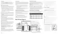
RS1 – RS2 – RS+V: Remote Sensor Bus
DAY
62˚F
82˚F
62˚F
82˚F
Used for connection of a wide variety of NetX™ remote
sensors, allowing installation flexibility and additional
information from the communications bus. It also allows the
thermostat to be placed in an area away from view.
(Schedule 2)
(17˚C)
(28˚C)
(17˚C)
(28˚C)
EVENING
70˚F
78˚F
70˚F
78˚F
LED1 / Filter Indicator
s
(Schedule 3)
(21˚C)
(25˚C)
(21˚C)
(25˚C)
NIGHT
62˚F
82˚F
62˚F
82˚F
If selected by software, the Filter Icon
will illuminate when a
s
(Schedule 4)
(17˚C)
(28˚C)
(17˚C)
(28˚C)
signal is received from the Terminal LED1 on the Terminal
block. This indicates the filter needs to be changed. Otherwise,
the status of the Terminal LED1 will be reported on the Status
Update page of the thermostat.
Basic Wiring Diagram
LED2 / Service Indicator
N
* There will be two (2) wires in the R and
the 24V(c) terminals.
If selected by the software, the Service Indicator icon
will
N
WIFI STAT
illuminate when a signal is received from Terminal LED2 on the
terminal block. This terminal is normally connected to the L
terminal on a heat pump. When a signal is received, the
** X7 models only. Connection and feature
dependent on user settings and HVAC equipment.
INPUT,
OCCUPANCY,
X-Series
*** X7 models only. Connection and feature
dependent on user settings and HVAC equipment.
WRENCH icon
will display on the thermostat screen. This
N
SETUP
indicates that service is required.
SENSOR
CONNECTIONS
HVAC CONNECTIONS
Auxiliary/Emergency Heat Indicator
Q
**K - Independent Relay,
24Vac INPUT #1
H - Humidify, D - Dehumidify
The thermostat is equipped with Emergency Heat icon
in
Q
L E D 1
L E D 2
C L K 1
C L K 2
R S 2
R S 1
R S + V
X 2
K / H / D
K/H/D
COMPRESSOR #2
24Vac INPUT #2
OCCUPANCY IN ( + )
the Main Status Icons area on the faceplate that indicates
when the system has engaged auxiliary heat mode or
emergency heat mode.
Y2
HEAT #1 or AUX/EMER HEAT
W1
Y 2
W 1
HVAC
Equipment.
OCCUPANCY IN ( – )
COMPRESSOR #1
Y1
Y 1
REMOTE SENSOR BUS - RTN
REMOTE SENSOR BUS - DATA
REMOTE SENSOR BUS - PWR
FAN
24 VAC*
G
R
G
Random Restart
1
R
Line
Voltage
2 4 V
2 4 V ( c )
O / W 2
B
After a power failure, the thermostat will delay the heating/
cooling equipment start-up by 1-24 seconds. When multiple
NetX™ X-Series thermostats are used, this minimizes the ‘in
rush’ current (electric power usage) as it reduces the number of
HVAC units that will be turned on simultaneously.
COMMON*
C
HEAT #2 or
O
X 1
REVERSING VALVE
B
K2 Independent Relay***
K 2
24 Vac
Transformer
Note: Check Heat Pump Installation Instructions
for reversing valve connection, either ‘O’ or ‘B’.
Page 3
| General | Details |
|---|---|
| Name | network thermostat NetX X Series Thermostat Instruction Manual |
| Make | Network Thermostat |
| Language | English |
| Filetype | PDF (Download) |
| File size | 0.28 MB |
 (1 votes, average: 5.00 out of 5)

Network Thermostat X7-Series Thermostat Installation Guide

Network Thermostat X7C-WIFI Smart Touchscreen Thermostat Instruction Manual

Network Thermostat X5-WIFI Smart Touchscreen Thermostat Instruction Manual

Network Thermostat NetXTM X-Series Thermostat Installation Guide

network thermostat NetX X5-CFA Universal Setback Thermostat Instruction Manual

network thermostat NetX X-Series Ethernet Thermostat Owner’s Manual

network thermostat X-Series Ethernet Thermostat Instruction Manual

Network Thermostat NetX X7 Series Thermostat Instruction Manual

network thermostat X X7-WIFI Smart Touchscreen Thermostat Instructions


tecnoswitch EN60730-1 Electronic Recessed Thermostat User Guide

BEOK CONTROLS BOT-R6W Boiler Thermostat User Guide

White Rodgers 1E78 5 2 Day Programmable Thermostat Instruction Manual

Beca BAC-7000 Smart Knob Thermostat User Guide

hansgrohe 15754000 Metris Classic Ecostat Classic High Flow Thermostat Instruction Manual

Meross MTS960 Smart Wi-Fi Socket Thermostat Instruction Manual

SALUS TS600 Wireless Temperature Sensor Thermostat User Guide

Danfoss RET230 HCW-1 Electronic Heat Cool Thermostat User Manual

Danfoss RT 9E Thermostat Installation Guide

sygonix 2522212 Installable Thermostat Instruction Manual