
neptronic TFC54F3X1 Fan Coil Thermostat Installation Guide
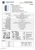


Fan Coil Thermostat
Specification and Installation Instructions
Programming mode
When in this mode this symbol
is displayed. Please press on button
to advance to the next program function, press on
button to return to preceding stage and press on button or to change value. You can leave the programming mode at any
time, changed values will be recorded.
Step
D
i
s
p
l
a
y
Description
Internal temperature sensor Calibration:
Values
Display switches between “tS1” and temperature read by internal
temperature sensor.
Range: 10 to 40ºC [50 to 104ºF]
(max offset 5ºC)
Increment: 0.1ºC [0.2ºF]
You can adjust the calibration of the sensor by comparison with a known
thermometer. For example if thermostat has been installed in an area where
temperature is slightly different than the room typical temperature
(thermostat place right under the air diffuser).
Minimum setpoint:
Display switches between “Stp” and the minimum setpoint temperature. MIN
symbol is also displayed.
Please select the desired minimum setpoint temperature.
The minimum value is restricted by the maximum value (step #3)
Maximum setpoint
Display switches between “Stp” and the maximum setpoint temperature.
MAX symbol is also displayed.
Please select the desired maximum setpoint temperature.
The maximum value is restricted by the minimum value (step #2)
Locking the setpoint :
1
Minimum range
10 to 35ºC [50 to 95ºF]
Increment: 0.5ºC [1ºF]
Default value: 15ºC [59ºF]
2
3
Maximum range
10 to 35ºC [50 to 95ºF]
Increment: 0.5ºC [1ºF]
Default value: 30ºC [86ºF]
Display switches between “LOC” and “Stp”.
You can lock or unlock the setpoint adjustment by end user. If locked the
lock symbol will appear.
If you do not want to lock setpoint adjustment by end user, go directly to
step #5.
Locking the setpoint (cont’d):
Select the desired locked setpoint temperature; this one should be within
the temperature range.
4A
4B
5
Default value: Unlocked
Setpoint range : 10 to 35ºC [50 to 95ºF]
Increment: 0.5ºC [1ºF]
Default value: 22ºC [72ºF]
Adjust the control mode:
Display switches between “CtL” and “Aut”.
Select which control mode you want to authorize: Automatic, cooling or
heating, heating only or cooling only.
If you want to authorize this entire mode, choose Automatic mode.
Default value: Cooling only
Set On/Off function enable or disable:
Display switches between “OFF” and “ena”.
You can enable or disable the Automatic mode adjustment by end user.
Default value: Enable
6
7
Set 2 pipes or 4 pipes:
Display switches between “Pno” and “2P”.
Select which number of pipes you want to use: 2 pipes or 4 pipes.
If you have selected the 4 pipes, go directly to step #12.
Default value: 2 pipe
Change over mode selection:
Display switches between “COc” and “nc”.
Please select mode of change over between contact normally cool or
contact normally heat or external sensor.
Note: This selection will affect “AO1”
If normally cool “nc” is selected, heating mode will be activated upon closing
of contact. If normally heat “nh” is selected, cooling mode will be activated
upon closing of contact.
8A
If external sensor “tS” is selected, heating mode will be activated when
temperature read by external sensor is above the Change Over SetPoint
temperature “tCo”, and cooling mode will be activated when temperature
read by external sensor is under “tCo”, see step #8B.
If “tS” is not selected, go directly to step #9.
Default value: Normally cool
Change over setpoint temperature: (If “tS” has been selected at step #8A)
Display switches between “tCo” and the change over setpoint temperature
selected.
Please select the change over setpoint temperature.
Note: heating mode will be activated when temperature read by external
sensor is above the change over setpoint temperature “tCo”, and cooling
mode will be activated when temperature read by external sensor is under
“tCo”.
Range: 10 to 40ºC [50 to 104ºF]
Increment: 0.5ºC [1ºF]
Default value: 24ºC [75ºF]
8B
8C
Change over temperature sensor Calibration:
Display switches between “COs” and the temperature read by the change
over temperature sensor (if connected).
You can adjust the calibration of the change over sensor by comparison
with a known thermometer.
Range: 10 to 40ºC [50 to 104ºF]
(max offset 5ºC)
Increment: 0.1ºC [0.2ºF]
Display:
0ºC [32ºF], resistance will be infinite.
50ºC [122ºF], resistance will be short
circuited.
Page | 3

| General | Details |
|---|---|
| Name | neptronic TFC54F3X1 Fan Coil Thermostat Installation Guide |
| Make | neptronic |
| Language | English |
| Filetype | PDF (Download) |
| File size | 0.5 MB |
 (1 votes, average: 5.00 out of 5)
 Loading...


neptronic STS3 Series Wall Thermostat Instruction Manual

neptronic ITO3-C Wall Thermostat Owner’s Manual

neptronic TMA54-EXT1 Thermostat Instruction Manual


NEOMITIS PRG7 RF 7 Day Two Channel Programmer with RF Room Thermostat Instruction Manual

Honeywell PRO 1000 Series Non-Programmable Thermostat Instruction Manual

Sygonix 2992337 DIN Rail Mounted Heating And Cooling Thermostat User Manual

BOSCH Thermostat atmosphere Smart Home 230 V Instruction Manual

Honeywell TH9320WF Smart Thermostat 9000 Color Touchscreen Installation Guide

YOLINK YS4003-UC Smart Thermostat User Guide

resideo T3 Programmable Thermostat Installation Guide

Honeywell TH6320ZW2003 Pro Z-Wave Programmable Thermostat Installation Guide

HYSEN HY02DB-WIFI Wifi Plug In Thermostat User Manual

HEATIT 54 304 59 DIN Smart Thermostat Installation Guide