neptronic TFC54F3X1 Fan Coil Thermostat Installation Guide


Fan Coil Thermostat
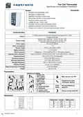
Specification and Installation Instructions
Mounting Instructions
A
B
C
D
E
CAUTION: Risk of malfunction. Remove power prior to separate thermostat cover from its base.
A. Remove the screw (captive) holding the base and the front cover of the thermostat.
B. Lift the front cover of the thermostat to separate it from the base.
C. Pull wire through the base hole.
D. Secure the base to the wall using wall anchors and screws (supplied). Make the appropriate connections.
E. Mount the control module on the base and secure using the screw.
Terminal description
Terminals
Fan option
Common (COM)
24 Vac (24Vac)
Sensor (EXT. TS)
NSB input (NSB. INP)
Analog output 1 (AO1)
Analog output 2 (AO2)
Digital output 1 (DO1)
Digital output 2 (DO2)
2 Pipe
2spd
4 Pipe
2spd
1 spd
3spd
1 spd
Common
24 Vac
Change over temp. sensor or contact
3spd
1
2
3
4
5
6
7
8
9
External temperature sensor
Night set back input
Cool/Heat
Reheat
Heat
Cool
-
-
-
High
Medium
Low
-
-
High
Medium
Low
High
Low
-
1 speed
High
Low
Digital output 3 (DO3) 1 speed
Settings on PC Board
Mode Selection (JP1)
Jumper (JP1) on RUN:
Thermostat is in operation mode.
Digital output
signal selector
JP1
PGM
Thermostat must be set in this mode to operate properly.
If not locked, setpoint, control mode and speed fan (Heating
& Cooling ON, Cooling only ON or Heating only ON) may be
modified by end user.
RUN
JP2
PGM
COM
Mode selector
24VAC
EXT.TS
JP1
Jumper (JP1) on PGM:
Thermostat is set in Programming mode.
Refer to following section about all settings description
NSB.
INP
RUN
PGM
AO1
AO2
Connecting
strip
Digital output signal selection (JP2)
DO1
DO2
DO3
Temperature
sensor
JP2
Jumper (JP2) on 24Vac:
All digital output signal is linked to 24 Vac.
24VAC
JP2
Jumper (JP2) on COM:
All digital output signal is linked to common.
TB1
COM
Page | 2
| General | Details |
|---|---|
| Name | neptronic TFC54F3X1 Fan Coil Thermostat Installation Guide |
| Make | neptronic |
| Language | English |
| Filetype | PDF (Download) |
| File size | 0.5 MB |


neptronic STS3 Series Wall Thermostat Instruction Manual

neptronic ITO3-C Wall Thermostat Owner’s Manual

neptronic TMA54-EXT1 Thermostat Instruction Manual


Honeywell TH8000 Vertical Non Programmable Thermostat Installation Guide

SALUS IT800 WIFI Smart Thermostat Installation Guide

HYSEN HY02B05RF Wireless Heating Thermostat User Manual

KOnighaus Infrarot Smart Thermostat User Guide

SCHRACK TECHNIK EV103311 Analog Thermostat User Manual

SALUS RT510 Thermostat Instruction Manual

Drayton 2290M Digistat 3rd Generation Programmable Room Thermostat Installation Guide

Gigaset Thermostat Instruction Manual

DELTA DORE Tybox 5701FP Pilot Wire Thermostat User Guide

SECURE H3747 Smart Programmable Thermostat Installation Guide