neptronic TFC54F3X1 Fan Coil Thermostat Installation Guide
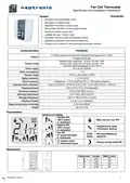


Fan Coil Thermostat
Specification and Installation Instructions
Feature:
TFC54F3X1
•
•
•
•
•
•
•
•
•
Selectable analog and digital output
Selectable fan speed contact
Selectable Fahrenheit or Celsius scale
Manual Night Set Back override (programmable)
Multi level lockable access menu
Lockable Set point / Control mode
Selectable internal or external temperature sensor
Selectable proportional control band & dead band
Change over by contact or external temperature sensor available
TFC54F3X1
Technical Data
2 Analog outputs (cooling and/or heating and/or change over 0-10Vdc)
3 Digital outputs (fan)
Outputs
Resistive load: rated load: 1.0 Amp / 24 VAC / VDC
Inductive load: rated load: 0.3 Amp / 24 VAC / VDC
maximum switching capacity: 30 VA / 24 W
Contact rating
Power supply
Power consumption
Setpoint range
22 to 26 Vac 50/60Hz
1 VA
10ºC to +35ºC [50ºF to 95ºF]
Display resolution
+/-0.1ºC [0.2ºF]
Control accuracy
Temperature: +/-0.5ºC [0.9ºF] @ 22ºC [71.6ºF] typical calibrated
Type G, 0ºC [32ºF] = 29.49 kΩ, 25ºC [77ºF] = 10 kΩ, 50ºC [122ºF] = 3.893 kΩ,
0.5ºC to 5ºC [1ºF to 10ºF] adjustable
0.8 mm2 [18 AWG] minimum
External sensor thermistor
Proportional band
Electrical connection
Operating temperature
Storage temperature
Relative Humidity
0ºC to 50ºC [32ºF to122ºF]
-30ºC to +50ºC [-22ºF to +122ºF]
5 to 95 % non condensing
Degree of protection of housing
Weight
IP 30 to EN 60529
80 g. [0.18 lb]
Presentation
Symbols on display
Cooling ON
100% output
A: Automatic
Heating ON
100% output
A: Automatic
Fan ON
Menu set-up Lock ON
Programming mode
(Technician setting)
Minimum/Maximum
setpoints
3rd speed activated
A: Automatic
ºC: Celsius scale
ºF: Fahrenheit scale
Energy saving mode ON
or
Dimensions
Dimension Inches
Metric (mm)
A
B
C
D
3.00
3.00
1.00
2.36
78
78
24
60
B
D
A
C
TFC54F3X1-231222
1

| General | Details |
|---|---|
| Name | neptronic TFC54F3X1 Fan Coil Thermostat Installation Guide |
| Make | neptronic |
| Language | English |
| Filetype | PDF (Download) |
| File size | 0.5 MB |


neptronic STS3 Series Wall Thermostat Instruction Manual

neptronic ITO3-C Wall Thermostat Owner’s Manual

neptronic TMA54-EXT1 Thermostat Instruction Manual

neptronic TFC54F3X1 Fan Coil Thermostat Installation Guide Overview
Summary of Contents
- Page 1: Fan coil thermostat specification and installation instructions Feature: TFC54F3X1 Selectable analog and digital output Selectable fan speed contact Selectable Fahrenheit or Celsius scale Manual night set back override (programmable) Multi level lockable access menu Lockable set point/control mode Selectable internal or external temperature sensor Selectable proportional control band & dead band Change over by contact or external temperature sensor available Technical data 2 analog outputs (cooling and/or heating and/or change over 0-10Vdc) 3 digital outputs (fan) Outputs resistive load: rated load: 1.0 Amp / 24 VAC / VDC Inductive load: rated load: 0.3 Amp / 24 VAC / VDC Maximum switching capacity: 30 VA / 24 W Setpoint range: 10ºC to +35ºC [50ºF to 95ºF] Control accuracy: Temperature: +/-0.5ºC [0.9ºF] @ 22ºC [71.6ºF] typical calibrated Operating temperature: 0ºC to 50ºC [32ºF to 122ºF] Storage temperature: -30ºC to +50ºC [-22ºF to +122ºF] Relative humidity: 5 to 95 % non condensing Degree of protection of housing: IP 30 to EN 60529 Weight: 80 g. [0.18 lb]
- Page 2: Fan coil thermostat specification and installation instructions provide essential guidance for mounting and connecting the device. Remove power prior to separating the thermostat cover from its base to avoid malfunction. The front cover of the thermostat can be lifted after removing the captive screw. Secure the base to the wall using the supplied wall anchors and screws. Make the appropriate connections after pulling the wire through the base hole. Mount the control module on the base and secure it using the screw. Terminal descriptions include various outputs and inputs such as common, 24 Vac, and external temperature sensor. Mode selection can be adjusted using jumper settings on the PC board for operation or programming mode. End users may modify setpoint, control mode, and fan speed if the thermostat is not locked. Digital output signal selection can be configured through jumper settings to link signals to either 24 Vac or common.
- Page 3: Fan coil thermostat specification and installation instructions. When in programming mode, specific symbols are displayed to navigate through functions. The internal temperature sensor can be calibrated with a known thermometer. Minimum and maximum setpoint temperatures can be adjusted within specified ranges. Setpoint locking allows control over user adjustments, with options for locking or unlocking. Control modes include automatic, cooling, heating only, or cooling only. The On/Off function can be enabled or disabled for automatic mode adjustments. Users can select between 2 pipes or 4 pipes for operation. Changeover mode selection affects how the system responds to temperature changes. Calibration for the changeover temperature sensor can also be adjusted.
- Page 4: Fan coil thermostat specification and installation instructions. Set local reheat On/Off or TPM if you have selected 2-pipe control mode. Display switches between “LHt” and “OFF”. Select which signal output you want for AO2. Proportional band for local reheat (AO2) ranges from 0.5 to 5.0ºC. Dead band for local reheat (AO2) ranges from 0.3 to 5.0ºC. Internal/external temperature sensor selection is available. External temperature sensor calibration can be adjusted by comparison with a known thermometer. Proportional band 1 in heating and cooling ranges from 0.5 to 5.0ºC. Set fan speed automatic mode enable or disable.
- Page 5: Fan coil thermostat specification and installation instructions. Time out fan contact displays the automatic shutoff delay value when there is no demand. Select the desired value of the automatic shutoff delay. Fan speed contact displays the speed of the fan. Select which speed contact you want: speed 1, speed 2, or speed 3. Night set back derogation time displays the derogation time in minutes. Select the desired derogation time; if OFF is selected, the thermostat is off when NSB is activated. Heating setpoint during night set back displays the value of the heating setpoint temperature. Cooling setpoint during night set back displays the value of the cooling setpoint temperature. Range for cooling setpoint is 10 to 35ºC [50 to 95ºF] with a default value of 28ºC [82ºF].
- Page 6: Fan coil thermostat specification and installation instructions outline the operation mode and display features. At powering up, the thermostat will light the display and activate all LCD segments for 2 seconds. To illuminate the LCD, press the designated buttons, and it will light for 8 seconds. In operation mode, the thermostat automatically displays the temperature read. To change the temperature scale between ºC and ºF, press both specified buttons for 3 seconds. To display the setpoint, press the button twice, and it will be shown for 5 seconds. When in night set back mode, the NSB symbol is displayed, indicating adjusted setpoints for cooling and heating. To change the control mode, press the designated button to choose from automatic cooling or heating, off, cooling only, or heating only. To change the fan speed mode, press the specified button to select from automatic speed, low speed, medium speed, or high speed. Wiring and schematic details are provided for line voltage and time clock connections.
- Page 7: Page 7
- Page 8: Recycling at end of life: please return this product to your Neptronic local distributor for recycling. If you need to find the nearest Neptronic authorized distributor, please consult the website.

ROMA HEATING RWI5 Wi5 Wi-Fi Digital Heating Thermostat User Manual

Wengart TP808-3 7 Day Programmable Thermostat User Manual

Danfoss DEVIreg 530 Electronic Thermostat Installation Guide

Uponor T-247 BUS Smatrix Base Thermostat Installation Guide

Roth 1135006445 Wireless Room Thermostat Touchline 230 V Instruction Manual

EMOS P56201UF Floor Heating Thermostat Instruction Manual

Danfoss RET230P Electronic Thermostat Instruction Manual
terneo v3G33 Simple Heat Control Thermostat Instruction Manual
STELPRO STE241 Low Voltage 24V Electronic Thermostat User Guide

SIEMENS TH192 HC Heating-Cooling Room Thermostat Instruction Manual