Home > NEOMITIS > NEOMITIS PRG7 RF 7 Day Two Channel Programmer with RF Room Thermostat Instruction Manual
NEOMITIS PRG7 RF 7 Day Two Channel Programmer with RF Room Thermostat Instruction Manual

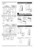


INSTALLATION - PROGRAMMER
MOUNTING OF WALL MOUTING PLATE
For best performance, do not mount the programmer on metal wall boxes and leave at
least 30 cm distance from any metal objects including wall boxes and boiler housing.
INSTALLATION INSTRUCTIONS
The digital programmer is fixed on the wall with the wall plate which is supplied with
the product.
1- Unscrew the 2 screws under the
2- Remove the wall plate from the
programmer.
programmer.
PRG7 RF
7 DAY TWO CHANNEL PROGRAMMER
WITH RF ROOM THERMOSTAT
x2
3- Secure the wall plate with the two
screws provided using the horizontal
and verꢁcal holes.
4- In case of surface mounꢁng, a knock
out area is provided on the wall plate
and on the corresponding area of the
programmer.
INSTALLING BATTERY
TABLE OF CONTENTS
Programmer baꢂery
access
Pack contains ............................................................................................1
Installaꢀon - Programmer..........................................................................1
Mounꢀng of wall mouꢀng plate .......................................................................................1
Installing baꢁeries.............................................................................................................1
Wiring ...............................................................................................................................1
Mounꢀng of the Programmer...........................................................................................2
Installaꢀon - Thermostat ...........................................................................2
Installing baꢁeries.............................................................................................................2
Mounꢀng of thermostat....................................................................................................2
Pairing procedure..............................................................................................................3
Installer seꢁngs ........................................................................................3
WIRING
Advanced installer seꢂng.................................................................................................3
All electrical installaꢀon work should be carried out by a suitably qualified
Electrician or other competent person. If you are not sure how to install
this programmer consult either with a qualified electrician or heaꢀng En-
gineer. Do not remove or refit the appliance onto the backplate without
the mains supply to the system being isolated.
Technical specificaꢀons .............................................................................4
PACK CONTAINS
All wiring must be in accordance with IEE regulaꢀons. This product is for fixed wiring
only.
• Internal wiring
N = Neutral IN
Note: The unit is double in insulated so
does not require an earth but a terminal
is supplied for the spare wire.
L
= Live IN
1
2
3
4
= HW/Z2: Normal close output
= CH/Z1: Normal close output
= HW/Z2: Normal open output
= CH/Z1: Normal open output
Clock
L
OFF
ON
OFF
ON
x
1
x1
x1
Programmer
Thermostat
Thermostat table stand
N
1
2
3
4
6A
max
HW
OFF OFF
CH
HW
ON
CH
ON
N
L
220V-240V~
50Hz
x2
x4
x4
AA Baꢀeries (LR6)
Screw Anchor
Screws
1
P
R
G
7
R
F
B
N
E
O
E
N
G
C
P
V
0
1
0
1
0
7
2
0
2
1

| General | Details |
|---|---|
| Name | NEOMITIS PRG7 RF 7 Day Two Channel Programmer with RF Room Thermostat Instruction Manual |
| Make | NEOMITIS |
| Language | English |
| Filetype | PDF (Download) |
| File size | 2.63 MB |


NEOMITIS RTE7OTA Wired Digital 7 Day Programmable Smart Room Thermostat Instruction Manual

Neomitis RTMA Mechanical Room Thermostat Instruction Manual

NEOMITIS RTE7D, RTE7BD Wired Digital 7 Day Programmable Room Thermostat Instruction Manual

NEOMITIS Rtaneoa Wired Analog Room Thermostat Instruction Manual

NEOMITIS RTE7SD Mains Powered Digital 7 Day Programmable Room Thermostat Instruction Manual

NEOMITIS RTE0RFA Wireless Digital Room Thermostat and Receiver Instruction Manual

NEOMITIS RTE0B Wired Digital Room Thermostat Installation Guide

NEOMITIS RTUa Mechanical Room Thermostat Instruction Manual

NEOMITIS PRG7 RF 7 Day Two Channel Programmer with RF Room Thermostat Instruction Manual Overview
Summary of Contents
- Page 1: Installation instructions for the digital programmer include mounting the wall plate supplied with the product. For optimal performance, avoid mounting the programmer on metal wall boxes and maintain a distance of at least 30 cm from metal objects. All electrical installation work should be performed by a qualified electrician or competent person. The unit is double insulated and does not require an earth connection, but a terminal is provided for a spare wire. Wiring must comply with IEE regulations, and this product is intended for fixed wiring only. The pack contains AA batteries, screws, and a screw anchor for installation. The programmer features a two-channel setup with a room thermostat. Ensure the mains supply to the system is isolated before removing or refitting the appliance onto the backplate. The installation process includes securing the wall plate with screws and ensuring proper battery access. A knock-out area is provided on the wall plate for surface mounting.
- Page 2: Mounting of the programmer involves replacing it on the wall and securing it with screws. Wiring diagrams are provided for a 3 port system. Installation of the thermostat requires removing the battery cover and inserting two AA batteries while noting the correct polarity. The thermostat must be mounted on the wall by unscrewing the screws and securing the wall plate with provided screws. Boiler and pump connections are detailed for the 2 port system. The document includes specifications for voltage and frequency. The programmer model mentioned is PRG7RF, a 2 channel programmer. Battery installation instructions emphasize the importance of correct polarity. The mounting process includes both horizontal and vertical holes for secure installation. Zone valve connections are indicated for proper setup.
- Page 3: Secure the thermostat by screwing the locking screws under the thermostat. The programmer and thermostat RF icon will be solid when pairing is complete and normal display is returned. If you want to check the signal strength, press and release the RF test button on the thermostat. Recommended locations for your thermostat include being installed approximately 1.5 m above floor level on an inside wall, away from direct sunshine and any other sources of heat or cold. Advanced settings can be modified by pressing until the correct option is in display. Select gravity/pumped mode to ensure proper operation of the product. The thermostat measures the temperature of the place where it is installed and does not account for temperature differences in different locations. To bond the programmer and thermostat together, move the mode sliders to the OFF position and then move the program slider to the RUN position. Press and hold the RF test button until Pair is shown in the display to initiate pairing. The pre-set value for the clock is 12 hours, which can be changed to 24 hours.
- Page 4: Auto Summer/Winter change over default is ON. Maximum range in the home is 15m, varying by building construction and environment. Power supply is 220V-240V/50Hz. Output per relay is 3(2)A, 240V/50Hz. Manual temperature setting range is from +5°C to +30°C. Battery life is approximately 2 years. You can adjust the number of ON/OFF switching time periods, with a pre-set number of 2. The digital programmer can manage Central Heating and Hot Water or 2 zones. The backlight can be switched off, with a pre-set value of ON. The product must be disposed of at a special recycling point at the end of its useful life.
- Page 5: controls and display programmer operating lcd display 7 day two channel programmer programming sliders sequences thermostat overview initial power up thank you for purchasing our PRG7 RF it is this ease of operation that is intended to make your life easier and help you save energy and money.
- Page 6: - After 2 seconds, the LCD will show the default time and day. - Within 1 minute, press and hold the RF Test button on the thermostat until Pair is shown in the display. - The pairing icon will be flashing. - A low battery level indicator will appear when the battery must be changed. - The programmer and thermostat RF icon will be solid when pairing is complete. - To start, insert the two AA batteries provided into the battery compartment. - The PRG is already set with the correct date and time. - Move the Programming slider to position to set the CH/Z1 and HW/Z2 programming. - The thermostat and the programmer are not bonded together at the factory. - Default schedule includes two On/OFF periods starting at 06:30 am and ending at 08:30 am.
- Page 7: The current program can be copied to the next days. Press Yes to copy or No to program manually the next day. Advance mode allows you to switch ON the system in advance until the next On/OFF period end time. Holiday mode allows you to switch off the heating and hot water for a specified number of days, adjustable between 1 and 99 days. Constant mode means the system is permanently turned ON. All day mode means the system turns ON from the first On period start time until the last Off period end time of the current day. Automatic mode means the unit is controlling to the programming that has been selected. Permanent Off mode means the system stays Off permanently, but the boost mode can still be used. Review mode allows you to review all programming in one time, starting from the beginning of the week. Boost mode allows you to switch ON for 1, 2, or 3 hours temporarily. The desired temperature can be set by turning the dial clockwise to increment or counter-clockwise to decrement.
- Page 8: Factory settings Troubleshooting Display disappears on programmer: Check fused spur supply. Check that the thermostat is calling for heat. If no increase, set temperature. Check the position of the batteries. Heating does not come on: If the CH Indicator light is on, it is unlikely to be a fault with the programmer. If the CH indicator light is NOT ON, check the programme then try BOOST. Nothing in the display: Check the position of the batteries. Check that your room thermostat is calling for heat. Check that the boiler is on. Hot water does not come on: If the HW Indicator light is on, it is unlikely to be a fault with the programmer. If HW indicator light is NOT ON, check programme then try BOOST. You made a mistake while setting: All LCD display will be turned ON for 2 seconds and the factory settings will be restored. The system is not heating but is on: If an indicator light is on but the system remains cold, then you should contact your installer. Set date and clock: Move the Programming slider to position. The preset year is solid. What is a programmer? Programmers allow you to set ‘On’ and ‘Off’ time periods. What is PID: The PID feature works by using a formula to calculate the difference between the desired temperature setpoint and current ambient temperature.

tado Smart Radiator Thermostat Installation Guide

NIBE RMU S40 Room Thermostat Instruction Manual

Honeywell 69-2384ES-01 RTH111 Non Programmable Thermostat Installation Guide
Danfoss VICUX40F Icon Dial 230V Room Thermostat Installation Guide

Honeywell TH8000 Vertical Non Programmable Thermostat Installation Guide

DOMETIC 3313192.XXX Single Zone LCD Thermostat Instruction Manual

Honeywell RLV450 Programmable Thermostat

WILLIAMS P322016 Thermostat Instruction Manual

MERSCHEL iQ MD2 Wired Thermostat User Manual

GENERAL LIFE FH251S Underfloor Heating Thermostat User Manual