Home >
LUX > LUX TX500Ub Non Programmable Thermostat Instruction Manual
× 1. Cautions And Warnings (System Compatibility → Features → Tools You May Need → Mounting Location → Install Thermostat Base → Operating Instructions) 2. Cautions And Warnings (Battery Instructions → Electrical Rating → Thermostat Sensitivity → System Check → User Awareness → Installation Instructions) 3. Lcd Display Screen (System Mode → System Compatibility → Compatible With → Not Compatible With) 4. Features (Tools You May Need) 5. Mounting Location (Remove Old Thermostat) 6. Install Thermostat Base (Wiring Information → Connecting The Wires) 7. Wiring Diagram Notes (Technical Assistance → Terminal Letters → System Common Wire → Heat Pump Systems → Aux And Emergency Heat → Mechanical Clock Wires) 8. Wiring Diagrams (Conventional → Heat Pump → Heating → Cooling → Heating And Cooling) 9. Stage Or 2-stage, Heating Only (Factory Rh-rc Jumper Wire Installed → Optional System Common) 10. Hot Water Heating Only (Wire Zone Valve → System 24v Transformer → Optional System Common) 11. , 4 Wires (Stage, Cooling Only → Factory Rh-rc Jumper Wire Installed → System 24v → Air Conditioner → Fan Transformer) 12. Conventional (non Heat Pump) (Stage Heating And 1-stage Cooling → Factory Rh-rc Jumper Wire Installed → Optional System Common) 13. Conventional (non Heat Pump) (Stage Heating And 1-stage Cooling → Factory Rh-rc Jumper Wire Installed → Optional System Common) 14. Conventional (non Heat Pump) 1-stage Heating And 1-stage Cooling With Two Separate 24v Transformers (Factory Rh-rc Jumper Wire Removed → Optional System Common) 15. Single-stage Heat Pump System (With No Aux Or Emergency Heat → Customer Installed Y-w1 Jumper Wire → Factory Rh-rc Jumper Wire Installed → Reversing Valve → System 24v Fan → Heat Pump Transformer) 16. Heat / 1-cool, Heat Pump System (With Aux And Emergency Heat → Use 'o' Or 'b' Terminals, Never Both → Customer Installed Y-w1 Jumper Wire → Factory Rh-rc Jumper Wire Installed → Aux / Emerg. Heat → System 24v Transformer) 17. Install Batteries Into Thermostat (Gas / Elec Circuit Board Option ('g' Terminal Fan Operation) → Front Panel Items → Heat / Off / Cool, System Mode Switch → Auto / On, Fan Mode Switch) 18. Multi-function, Set Slide Switch (Up / Down Buttons → Hold Button → Emer Button → Next Button) 19. System Configuration And Setup Options (To Access The Setup Menu → Item #01 (clk = Clock Format) → Item #02 (tmp = Temperature Scale) → Item #03 (thermostat Type) → Item #04 (perd = Period Quantity) → Item #05 (rcv = Early Recovery)) 20. Item #07 (dlay = Delay Time) (Item #08, #09, #10 (cycl = System Cycle Duration) → Item #11 (stage-2 Offset)) 21. Operating Instructions (Set Day And Time → Heating And Cooling → Emergency Heat) 22. Lcd Display Backlight (Temperature Override → Temperature Hold → Static Notice) 23. Temperature Programs (Set Temperature Programs) 24. Advanced Features (Temperature Calibration → Temperature Limit Stops) 25. To Set The Cool Limit Stop (To Change The Temperature Stop Lock Code → If You Forget Your Temperature Stop Code) 26. Keypad Lockout (To Lock The Keypad → To Unlock The Keypad → Air Filter Monitor → To Set The Air Filter Duration) 27. To Reset The Filter Usage Counter (Hardware Reset → Software Reset → Compressor Protection Bypass) 28. Battery Replacement (Battery Graphic) 29. Technical Assistance (Limited Warranty) 30. Mercury Warning And Recycling Notice
Close
LUX TX500Ub Non Programmable Thermostat Instruction Manual
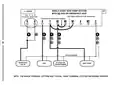
3, 4 WIRES
#3
1-STAGE, COOLING ONLY
Factory RH-RC Jumper Wire Installed
O
B
G
Y
RC
RH
W1
A
W2
C
G
F
Y
Y1
6
R
C
X
RC
V
B*
O
P
T
I
O
N
A
L
SYSTEM COMMON
SYSTEM 24V
AIR
CONDITIONER
FAN
TRANSFORMER
NOTE: THE BLACK TERMINAL LETTERS ARE TYPICAL, GRAY TERMINAL LETTERS ARE BRAND SPECIFIC
General Details Name LUX TX500Ub Non Programmable Thermostat Instruction Manual Make LUX Language English Filetype PDF (Download) File size 0.31 MB
Download PDF Loading...




 Loading...