LUX TX500Ub Non Programmable Thermostat Instruction Manual


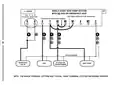


WIRING DIAGRAM NOTES:
(Important, please read all notes before connecting wires)
• If the information provided in the following wiring diagrams does not clearly
represent or match your system, please refer to the “TECHNICAL ASSISTANCE”
section of this manual, and contact us before removing any of your existing
thermostat wiring.
• All of the dashed wires shown in the wiring diagrams are either optional, or
their usage depends upon your specific system type or brand. For example:
Diagram #1 shows the fan wire as optional. If your system does not have a
fan, than this terminal will not be used.
• Terminal letters shown in black represent typical wiring applications.
Depending upon the brand of your specific system or thermostat, your terminal
letters may not match exactly. Terminal letters shown in gray represent other
possible wiring designations that you might see on your existing thermostat
terminals.
• The optional “C” terminal is used for powering the thermostat by the 24-volt
system, using the System Common wire. This can be used alone, or in
addition to installing batteries as a backup. NOTE: connecting the System
Common wire to the thermostat is not necessary for heating and cooling to
function properly.
• If your old thermostat has both a “Y” and “C” wire both present, then “C” is
most likely a System Common wire.
• For Heat Pump systems, you will use either the “O” terminal or the “B”
terminal on this thermostat, but not both. If your old thermostat has both an
“O” and a “B” wire present, then “B” is likely a System Common wire and may
be connected to the “C” terminal. Connecting a System Common wire to this
thermostat’s “B” terminal may damage the thermostat, and also your heating
and cooling system.
• Some Heat Pump systems have a wire for AUX electric heat (usually W2), and
also a separate wire for Emergency electric heat (usually E). This thermostat
uses the W2 terminal for both AUX and Emergency Heat. Tape off your “E”
wire, and confirm that all components function without it.
• If replacing an old thermostat that has a mechanical clock, there may be two
wires labeled as “C” for the clock power. Tape off these wires and do not
connect them to the “C” terminal of this thermostat.
7
| General | Details |
|---|---|
| Name | LUX TX500Ub Non Programmable Thermostat Instruction Manual |
| Make | LUX |
| Language | English |
| Filetype | PDF (Download) |
| File size | 0.31 MB |


LUX TX700U Universal Thermostat Instruction Manual

LUX TX1500E Programmable Thermostat Instruction Manual

LUX CAG1500 SERIES Smart Temp Electronic Thermostat Instruction Manual

LUX PSP511A Smart Temp Electronic Thermostat Instruction Manual

LUX PSP511A Series Programmable 5-2 Thermostat Instruction Manual

LUX PSPH521 Series Programmable Heat Pump Thermostat Instruction Manual

LUX DHP2120 Battery Powered Non Programmable Digital Heat Pump Thermostat Installation Guide

CH200SA Versatile Deluxe Low Voltage Thermostat Installation Guide

LUX TH10 Heating Only Mercury FREE Manual Thermostat Instruction Manual
LUX PSP511Ca Programmable Thermostat Instruction Manual


TROLEX TX2010 Surface Thermostat Instruction Manual

Honeywell TC500A-N Commercial Thermostat User Guide
PECO CONTROL SYSTEMS T8168B-2 BACnet IP Connection Thermostat Instructions

sinope TH1124NP Non Programmable Thermostat for Electric Heating Owner’s Manual

Blue Universal OH-1202 Touchscreen Thermostat Instruction Manual

Vaillant VRT 51f sensoROOM Wireless Room Thermostat Instruction Manual

ENGO CONTROLS EFAN-24W Fan Coil Thermostat User Guide

tado Smart AC Control V3+ Thermostat Instruction Manual
Danfoss VICUX40F Icon Dial 230V Room Thermostat Installation Guide

ESi ESRTP6C, ESRTP6CW Centro Prog Room Thermostat User Guide