LUX TX500Ub Non Programmable Thermostat Instruction Manual


TX500Ub
SMART TEMP® UNIVERSAL 5/2-DAY
PROGRAMMABLE OR NON-PROGRAMMABLE THERMOSTAT
(FOR BOTH CONVENTIONAL AND HEAT PUMP SYSTEMS)
INSTALLATION AND OPERATING INSTRUCTIONS
52134
IMPORTANT!
• Please read all of these instructions carefully before beginning
installation.
• Label every wire terminal designation on your existing thermostat wiring
before removing your old thermostat.
• Ignore the color of the wires since they may not comply with any
standard. Please connect wires using the terminal letter designations.
Thank you for your confidence in our product. To obtain the best results from
your investment, please read and follow the installation procedures carefully, and
one step at a time. This will save you time and minimize the chance of damaging
either the thermostat or possibly your heating and cooling system. These
instructions may contain information beyond that which may be required for your
particular installation.
CAUTIONS AND WARNINGS . . . . . . . . . . 2
SYSTEM COMPATIBILITY . . . . . . . . . . . . 3
FEATURES . . . . . . . . . . . . . . . . . . . . . . . 4
TOOLS YOU MAY NEED . . . . . . . . . . . . . . 4
MOUNTING LOCATION . . . . . . . . . . . . . . 5
REMOVE OLD THERMOSTAT . . . . . . . . . . 5
INSTALL THERMOSTAT BASE . . . . . . . . . 6
WIRING INFORMATION . . . . . . . . . . . . . . 6
WIRING DIAGRAMS . . . . . . . . . . . . . . . . 8
COMPLETE THE INSTALL . . . . . . . . . . . 17
FRONT PANEL ITEMS . . . . . . . . . . . . . . 17
SYSTEM CONFIGURATION AND SETUP
OPTIONS . . . . . . . . . . . . . . . . . . . . . . . 19
OPERATING INSTRUCTIONS . . . . . . . . . 21
TEMPERATURE PROGRAMS . . . . . . . . . 23
ADVANCED FEATURES . . . . . . . . . . . . . 24
BATTERY REPLACEMENT . . . . . . . . . . . 28
TECHNICAL ASSISTANCE . . . . . . . . . . . 29
LIMITED WARRANTY . . . . . . . . . . . . . . 29
MERCURY NOTICE . . . . . . . . . . . . . . . . 30
WARNING: Use Energizer® or DURACELL® Alkaline Batteries Only.
Energizer® is a registered trademark of Eveready Battery Company, Inc.
DURACELL® is a registered trademark of The Procter & Gamble Company
© 2014 LUX PRODUCTS CORPORATION. ALL RIGHTS RESERVED
h
t
t
p
s
:
/
/
m
a
n
u
a
l
-
h
u
b
.
c
o
m
/

| General | Details |
|---|---|
| Name | LUX TX500Ub Non Programmable Thermostat Instruction Manual |
| Make | LUX |
| Language | English |
| Filetype | PDF (Download) |
| File size | 0.31 MB |


LUX TX700U Universal Thermostat Instruction Manual

LUX TX1500E Programmable Thermostat Instruction Manual

LUX CAG1500 SERIES Smart Temp Electronic Thermostat Instruction Manual

LUX PSP511A Smart Temp Electronic Thermostat Instruction Manual

LUX PSP511A Series Programmable 5-2 Thermostat Instruction Manual

LUX PSPH521 Series Programmable Heat Pump Thermostat Instruction Manual

LUX DHP2120 Battery Powered Non Programmable Digital Heat Pump Thermostat Installation Guide

CH200SA Versatile Deluxe Low Voltage Thermostat Installation Guide

LUX TH10 Heating Only Mercury FREE Manual Thermostat Instruction Manual
LUX PSP511Ca Programmable Thermostat Instruction Manual

LUX TX500Ub Non Programmable Thermostat Instruction Manual Overview
Summary of Contents
- Page 1: SMART TEMP universal 5/2-day programmable or non-programmable thermostat installation and operating instructions. Please read all of these instructions carefully before beginning installation. Label every wire terminal designation on your existing thermostat wiring before removing your old thermostat. Connect wires using the terminal letter designations. These instructions may contain information beyond that which may be required for your particular installation. Cautions and warnings. System compatibility. Features. Tools you may need. Wiring information.
- Page 2: Cautions and warnings: This thermostat requires batteries to operate and failure or sub-standard performance of the batteries may impair or prevent the correct operation of the thermostat. Use Duracell or Energizer alkaline batteries only for all LUX thermostats requiring batteries. Be sure to change the batteries at least once a year, or whenever you see the LO BATT indication on the screen. The electrical rating for this thermostat is 1.5 Amps per terminal, with a maximum total load of 3.0A for all terminals combined. The thermostat contains parts that may wear out through use and are susceptible to failure if overloaded or used in a manner other than as indicated in the documentation. Check unoccupied residences regularly to ensure that all systems are operating properly. Check any heating/air-conditioning system including this product before operation and at regular intervals. Electrical interference, static electricity, failure or substandard performance of batteries, wiring defects in the installation and/or characteristics of the connected HVAC devices may prevent the system from regulating heating and cooling as anticipated. The thermostat is a sensitive device and dropping the product can cause damage to critical components. Persons with physical or mental limitations may not be able to promptly respond to a malfunction of the heating/air-conditioning system. All residents should be made aware of the potential in any system for malfunctions that could cause continuous heating or cooling. Read the instruction manual completely before installing the thermostat. You should consult a qualified HVAC technician or an electrician if you do not fully understand the installation instructions.
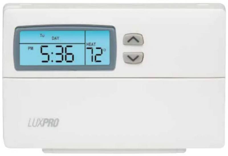
- Page 3: LCD display screen Fan mode System compatibility: The electrical rating for this thermostat is 1.5 Amps per terminal, with a maximum total combined load of 3.0A for all terminals combined. Compatible with most 24-volt heating and cooling systems. Compatible with 1 or 2 stage heat / 1 stage cool: gas, oil or electric systems. Compatible with 1 or 2 stage heat / 1 stage cool: heat pump systems. Compatible with 3-wire hydronic (hot water) zone valves. Compatible with gas millivolt heaters. Not compatible with 120/240 VAC line-voltage systems (without a transformer).
- Page 4: Features include 1 or 2-heat / 1-cool, 5/2-day programming. The device has universal compatibility for all system types. Weekdays and weekends can be programmed separately. It features an exclusive LUX Speed Slide for easy programming. Users can select periods per day (2 or 4) and choose between programmable or non-programmable operation. The display is a LuxLight EL lighted display. There is a programmable air filter life timer and a keypad lockout for unauthorized users. The device allows for manual temperature hold and temporary temperature override. It includes adjustable temperature differential and cycle-rate settings.
- Page 5: Mounting location: On replacement installations, mount the new thermostat in place of the old one unless the conditions listed below suggest otherwise. On new installations, please follow these general guidelines: Mount the thermostat on an inside wall, about 5 ft. (1.5m) above the floor. Do not locate the thermostat where air circulation is poor such as in a corner, alcove, or behind a door that is normally left open. Do not locate the thermostat where unusual heating or cooling conditions may be present, such as direct sunlight, above a lamp, television, or radiator, or on a wall next to an exterior door or window. Do not locate in a damp environment, as this can lead to corrosion that may shorten thermostat life. If painting or construction work is still ongoing, cover the thermostat completely or wait until this work is complete before installation. Warning: All wiring must conform to the local codes and ordinances that are in your particular location. Remove old thermostat: Turn OFF the electricity to all heating and cooling components. Do not turn the electricity back on until all work is completed. Remove the front portion of your old thermostat to expose the wiring connections. Write down the letters printed near each wire terminal that is used, and also the color of each wire that is connected to it. Carefully remove the wires one at a time, and bend them in a manner so that they do not fall back inside the wall. Do not allow bare wire ends to touch each other. Loosen the mounting screws for the old thermostat and carefully remove it from the wall.
- Page 6: Install thermostat base. Strip wire insulation leaving only 3/8 in. (9.5mm) bare wire ends, and clean off any corrosion present. Fill the wall opening with non-combustible insulation to prevent drafts from affecting the thermostat’s normal operation. Separate new thermostat housing using your thumb and index finger. Route the wires through the opening in the new thermostat base plate, and hold the base against the wall. If the previous holes cannot be used, hold the thermostat base against the wall so that it appears straight and level and mark for the new screw holes. Attach the base to the wall using the screws provided. When attaching the wires to the thermostat, ensure that the bare wire ends are held all the way into the terminal block while the screw is being tightened.
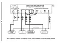
- Page 7: Wiring diagram notes are important to read before connecting wires. If the wiring diagrams do not match your system, refer to the technical assistance section before removing existing thermostat wiring. Dashed wires in the diagrams are optional or depend on your specific system type or brand. Terminal letters shown in black represent typical wiring applications, while gray letters indicate other possible designations. The optional C terminal powers the thermostat using the System Common wire, which is not necessary for heating and cooling to function properly. If both Y and C wires are present in your old thermostat, C is likely a System Common wire. For Heat Pump systems, use either the O or B terminal, but not both, as connecting a System Common wire to the B terminal may cause damage. Some Heat Pump systems have separate wires for AUX and Emergency electric heat, with this thermostat using the W2 terminal for both. If replacing a thermostat with a mechanical clock, do not connect wires labeled as C for clock power to the C terminal of this thermostat.
- Page 8: Wiring diagrams provide a visual representation of system types and descriptions. The document includes various conventional and heat pump configurations. Different pages are dedicated to specific heating and cooling setups. 1-stage or 2-stage heating systems are detailed. Zone valve configurations are outlined for heating systems. Cooling systems are categorized by 1-stage setups. Heating and cooling systems are described for both 1-stage and 2-stage heat. Two-transformer systems are also included in the diagrams. Emergency heat configurations for heat pumps are specified. The document serves as a comprehensive guide for wiring various HVAC systems.
- Page 9: 2-wire heat uses RH & W1. Factory RH-RC jumper wire installed. FAN wire may not be present in all systems. Note: The black terminal letters are typical, gray terminal letters are brand specific. 1-stage or 2-stage, heating only (including millivolt). Optional system common. System 24V transformer. Stage 1. Stage 2. Heater.
- Page 10: Hot water heating only with a 3-wire zone valve. Factory RH-RC jumper wire installed. Open = heat on. Close = heat off. Note: The black terminal letters are typical, gray terminal letters are brand specific. 3-wire zone valve. System 24V transformer. Optional system common. Wiring configuration includes various terminals labeled O, B, G, Y, RC, RH, W1, W2, C, R, W, A, and X. Indicates operation modes for heating control.
- Page 11: 3, 4 wires 1-stage, cooling only Factory RH-RC jumper wire installed System 24V air conditioner Fan transformer Note: The black terminal letters are typical, gray terminal letters are brand specific
- Page 12: Conventional (non heat pump) 1-stage heating and 1-stage cooling. Factory RH-RC jumper wire installed. Typical terminal letters are black; brand specific terminal letters are gray. System common air conditioner. 24V transformer. Fan. Heater. Optional. Wires configuration. Terminal designations.
- Page 13: Conventional (non heat pump) 2-stage heating and 1-stage cooling Factory RH-RC jumper wire installed Typical terminal letters are black Brand specific terminal letters are gray
- Page 14: Conventional (non heat pump) 1-stage heating and 1-stage cooling with two separate 24V transformers. Factory RH-RC jumper wire removed. The black terminal letters are typical, gray terminal letters are brand specific.
- Page 15: Single-stage heat pump system with no aux or emergency heat. Use “O” or “B” terminals, never both. Customer installed Y-W1 jumper wire. Factory RH-RC jumper wire installed. Black terminal letters are typical, gray terminal letters are brand specific. Reversing valve. System 24V fan. Heat pump transformer. Wiring configuration includes various terminals such as O, B, G, Y, RC, RH, W1, and others. Four or five wires are used in the system.
- Page 16: 5, 6 wires 2-heat / 1-cool, heat pump system with aux and emergency heat Use “O” or “B” terminals, never both Customer installed Y-W1 jumper wire Factory RH-RC jumper wire installed Note: The black terminal letters are typical, gray terminal letters are brand specific
- Page 17: Complete the install. Install batteries into thermostat: Install two brand new Energizer or Duracell “AA” size alkaline batteries into the thermostat’s battery compartment. Ensure the batteries are installed in the proper direction. Gas / electric circuit board option (“G” terminal fan operation): This setting is a plastic shorting cap called a jumper. This jumper must remain installed and set to either gas or electric for your system to work properly. When set to “gas”, the blower fan is controlled solely by the heating system itself. Systems that would typically use the “gas” setting include natural gas, propane, or oil furnaces, and boilers. When set to “elec”, the blower fan is controlled directly by the thermostat. This setting is required for heating systems that do not control their own fan, such as heat pumps. Front panel items: These items are located behind the door on the front of the thermostat. To open the door, pull outwards using the small indentation in the center of the top edge of the thermostat housing. Heat / off / cool, system mode switch: Set this switch to heat to control your heating system, and cool to control your cooling system. The off position will disable both the heating and cooling units. Auto / on, fan mode switch: When this switch is in auto, the blower fan will automatically cycle on and off while heating or cooling is running. When in the on position, the blower fan will run constantly.
- Page 18: The fan mode switch only works if your system provides a wire for the thermostat’s “G” wire terminal. The fan mode switch has no effect in systems that do not have a blower fan. The multi-function set slide switch provides an easy way to quickly access commonly used thermostat settings. This switch has four individual positions and should remain in the RUN position for the thermostat to control room temperature. The switch is only operable when the thermostat is in “Programmable” mode. The UP and DOWN buttons are used to adjust set temperatures, clock times, and days of the week. The hold button activates and deactivates the manual temperature hold feature. The EMER button enables emergency heat function for heat pump systems. The NEXT button is used while setting items such as software options and temperature program periods. Pressing the NEXT button will cycle through which item is flashing for adjustment.
- Page 19: System configuration and setup options are performed using a menu on the display screen. To access the setup menu, move the System Mode switch into the OFF position and hold down the EMER button for approximately 5 seconds until the screen changes. The menu starts with item #1 and is advanced to each following item by pressing the NEXT button. Item #01 (CLK = Clock format) offers options for standard AM/PM or military-time format. Item #02 (TMP = Temperature scale) allows for Fahrenheit or Celsius display of temperature values. Item #03 (Thermostat type) includes settings for a programmable routine or a manual non-programmable thermostat. Item #04 (PERD = Period quantity) provides options for four periods per day or two periods per day. Item #05 (RCV = Early recovery) affects how the thermostat transitions between periods and calculates recovery time. Item #06 (System mode) includes settings for heating systems that are not heat pumps or for heat pump systems.
- Page 20: ITEM #07 (DLAY = DELAY TIME): The thermostat waits 5 minutes before turning the system back on after it was last run. This internal delay prevents rapid cycling and provides equipment protection. The 5 minute setting is fine for most applications. ITEM #08, #09, #10 (CYCL = SYSTEM CYCLE DURATION): These settings control how frequently your heating/cooling system will be allowed to cycle on during room temperature control. The possible setting values are: 60, 30, 20, 15, 12, 10, 8, and 6. #08 = HEAT MODE, CYCLE DURATION #09 = COOL MODE, CYCLE DURATION #10 = EMERGENCY HEAT, CYCLE DURATION When the heating/cooling system turns on, it will remain running for as long as necessary to reach and maintain your target set temperature. ITEM #11 (STAGE-2 OFFSET): This setting is adjusted as a number from 0 to 9. This setting varies how low the room temperature must drop before the second heating stage becomes activated, if present. A lower number will make the second stage turn on sooner, providing increased comfort. A larger number will allow a greater decrease in room temperature before turning on the second heating stage, providing greater energy efficiency.
- Page 21: Operating instructions provide essential guidance for setting up and using the device. Set day and time by placing the Set Slide Switch into the DAY/TIME position. Adjust the day of the week using the UP or DOWN buttons while the day is flashing. Press NEXT to set the clock time, ensuring the AM/PM indication is correct. Basic operation of heating or cooling systems is achieved with the Set Slide Switch in the RUN position. Choose either HEAT or COOL on the System Mode switch to adjust temperature. The thermostat follows a default temperature routine preset from the factory. Emergency Heat mode can be activated with a single press of the EMER button while in normal Heat mode. In Emergency Heat mode, the thermostat will use only the Auxiliary Heat as the primary heating source. If a power loss occurs during Emergency Heat mode, the thermostat remains in that mode after power restoration.
- Page 22: Use Emergency Heat mode whenever the outside temperature is less than 32°F (0°C). The display screen is lighted to assist viewing at nighttime or in low light levels. Pressing any button will light the display for approximately 10 seconds. The set temperature can be temporarily changed while in Program RUN mode. The set temperature will return to the programmed value when the next program period starts. The word “OVERRIDE” will be shown in the display during a Temporary Override. A Temperature Hold maintains a fixed set temperature indefinitely. To enter Hold mode, press the HOLD button once and “HOLD” will appear in the display. If a power failure occurs during a Temperature Hold, the thermostat remains in Hold mode after power returns. It is advisable to install new batteries before leaving the thermostat in Hold mode for an extended duration.
- Page 23: Temperature programs include 4 separate periods for both heat and cool modes: MORN, DAY, EVE, and NITE. Heat programs are set in HEAT mode, while cool programs are set in COOL mode. If configured for only 2 periods per day, the thermostat will use only DAY and NITE periods. To set temperature programs, move the Set Slide switch to the TEMP PROG position. Programming starts with all weekdays, Monday through Friday. Use the UP/DOWN buttons to adjust the start time and set temperature for each period. After setting the NITE period for weekdays, the thermostat advances to the weekend program. The MORN period start time will flash for setting Saturday and Sunday. Return the Set Slide switch to the RUN position when finished.
- Page 24: Advanced features include temperature calibration and temperature limit stops. The internal temperature sensor is calibrated at the factory, and alterations are usually unnecessary. The temperature calibration feature allows manual offset of the measured temperature by up to plus or minus 5°F (3°C). This feature helps synchronize multiple thermostats in the same home. The temperature calibration setting will timeout after approximately 10 seconds without a button press. To change the temperature calibration, ensure the system mode switch is OFF and the set slide switch is in RUN. Press and hold both the UP and DOWN buttons for at least 5 seconds to access the calibration screen. There are two independent set temperature limit stops: a maximum heat set temperature and a minimum cool set temperature. The heat limit stop prevents the temperature from being adjusted higher than the set limit, while the cool limit stop prevents it from being adjusted lower. Each temperature stop is user adjustable in one-degree increments and protected by a selectable 2-digit code.
- Page 25: To set the heat limit, use the UP/DOWN buttons to adjust the maximum heat set temperature value. To set the cool limit, place the System Mode switch in the OFF position and the Set Slide switch in the RUN position. Press and hold the DOWN button while sliding the System Mode switch from OFF to COOL. Use the UP/DOWN buttons to select the proper code to access the cool limit setting. To change the temperature stop lock code, press and hold the NEXT button for at least 5 seconds. Use the UP/DOWN buttons to choose a new 2-digit code between “00” and “99”. If you forget your temperature stop code, it can be reset to the factory default “00”. Press and hold the NEXT and HOLD buttons together for at least 10 seconds to reset the code. The screen will display words “SET”, “STOP” and “LOCK CODE”, along with the new code of “00”. The screen will automatically return to the Normal Run screen in Off mode after resetting.
- Page 26: Keypad lockout allows you to lock the front panel buttons to prevent unauthorized tampering of thermostat settings. The keypad lock instructions must be performed within a 10-second timeframe. To lock the keypad, start with the System Mode switch in either the HEAT or COOL positions and the Set Slide switch in the RUN position. The locking sequence is NEXT, NEXT, NEXT, HOLD. To unlock the keypad, use the same sequence as locking. The air filter monitor helps track maintenance and replacement intervals for the system's filter. The monitor counts the duration of filter usage since the last reset. When the filter usage duration expires, FILTER will flash on the screen. To set the air filter duration, move the Set Slide switch to the AIR FILTER position. You can select the desired filter duration from options including OFF, 30, 60, 90, 120, 180, or 365 days.
- Page 27: To reset the filter usage counter, move the Set Slide switch to the “AIR FILTER” position. The three small digits at the top of the screen indicate the quantity of filter days remaining. Press both the UP and DOWN buttons together to reset the usage counter. Return the Set Slide switch to the RUN position when finished. The Hardware Reset button is located in the middle of the circuit board, just below the battery holder. Pressing the Hardware Reset button will perform an internal system check of the thermostat components. The temperature programs are not erased during a hardware reset, but the clock will need to be reset. A Software Reset erases all heating and cooling temperature programs and returns settings to factory defaults. To perform a Software Reset, ensure the Keypad Lockout is not enabled and move the System Mode switch to OFF. The optional compressor protection bypass feature allows temporary disabling of built-in compressor protection delays for diagnostics.
- Page 28: Battery replacement is necessary for reliable operation. Batteries should be replaced at least once per year or sooner if LO BATT appears. The batteries are located on the back of the thermostat’s circuit board. The front portion of the thermostat can be removed using the tabs on the top edge. Use only brand new Energizer or Duracell AA size alkaline batteries for replacement. Observe polarity markings in the battery compartment during installation. A visual indication of remaining battery life is available on the thermostat’s display screen. When new batteries are installed, the graphic indicates full battery life. As battery life decreases, the display will alternate between normal content and LO BATT. The thermostat can provide approximately two months of operation after reaching the LO BATT point.
- Page 29: Technical assistance is available for installation or usage problems. Contact the Technical Assistance department during regular business hours for help. Online technical assistance is available anytime on the company website. The limited warranty covers defects in materials or workmanship for three years from the original purchase date. The warranty does not cover damage from accident, misuse, or failure to follow installation instructions. Implied warranties are limited to three years from the original purchase date. Return malfunctioning units to the purchase location with proof of purchase. Refer to the technical assistance section before returning the thermostat. The purchaser assumes all risks and liability for damages resulting from installation and use. This warranty is applicable in the U.S.A. and Canada only.
- Page 30: Mercury is considered to be a hazardous material. If this product is replacing a thermostat that contains mercury in a sealed tube, contact your local waste management authority for instructions regarding recycling and proper disposal. It may be unlawful in your state to place it in the trash.

GENERAL MITRA 250S Digital Room Thermostat User Manual

GENERAL LIFE SENNA 300S Ignite Digital Room Thermostat User Manual

BEOK TS4 Series Wi-Fi Touch Screen Thermostat User Manual

THE HEATING COMPANY Slim and Compact WiFi Thermostat User Manual

TELUS Battery for Smart Thermostat Instructions

KETOTEK F0155 WiFi Thermostat Instruction Manual

INTIEL Controllers DT 3.1 Programmable Differential Thermostat User Guide
Roth Basicline Wired Thermostat Installation Guide

Honeywell Lyric Thermostat THP2400A1019 Installation Guide

SALUS CONTROLS IT800WIFI Smart Thermostat Installation Guide