
LoRaWAN MC-LW-FCT-01 MClimate Fan Coil Thermostat User Manual






MClimate Fan Coil Thermostat LoRaWAN®
User manual


| General | Details |
|---|---|
| Name | LoRaWAN MC-LW-FCT-01 MClimate Fan Coil Thermostat User Manual |
| Make | LoRaWAN |
| Language | English |
| Filetype | PDF (Download) |
| File size | 0.52 MB |
 (1 votes, average: 5.00 out of 5)
 Loading...

LoRaWAN MC-LW-FCT-01 MClimate Fan Coil Thermostat User Manual Overview
Summary of Contents
- Page 1: Page 1
- Page 2: Scan the QR code to access MClimate Fan Coil Thermostat LoRaWAN® extended documentation. For installation instructions, scan the QR code or visit the link next to it. Available in multiple languages including Bulgarian, Dutch, Czech, Polish, Finnish, Italian, Swedish, German, French, and Spanish. Need some help? For more product information and issues related to it, visit the provided resources.
- Page 3: What’s inside the box? Introduction Technical details, safety instructions, legal notices & compatibility Installation guide User interface guide Operating instructions Connectivity and smart building Wiring diagrams Wall mounting plate Secure bolt
- Page 4: Introduction Overview of the product The MClimate Fan Coil Thermostat (FCT) is a LoRaWAN thermostat for 2- and 4-pipe fan coil units, accommodating 1-3 speed or ECM fans. It enables room-by-room monitoring and control, enhances energy efficiency, and has great potential to reduce heating/cooling expenses significantly. With its 4.2” e-ink fast refresh display, it allows end-users to change the target temperature and see current indoor conditions. Its fully open and transparent communication protocol allows seamless integration into different systems including the MClimate Enterprise platform. MClimate’s ultimate aim is to help decarbonize buildings. The Fan Coil Thermostat unlocks great retrofitting opportunities for control and monitoring on a room-by-room basis. MClimate FCT can be integrated into existing BMS and BAS systems. Technical wiring diagrams for the different configurations are available further in the document.
- Page 5: Sensors: Temperature & Humidity Operating conditions: Operating temperature: 0°С to +50°С Operating humidity: 0-80% RH (non-condensing) Storage & Transport conditions: As per IEC 60721-3-1 IP rating: IP31 (EN60529) Mounting options: Screws and dowels on a wall or screws only on an electrical box Technical specifications: Designed and manufactured by MClimate™ in the EU Power supply: 110-240VAC, 50/60Hz, 50mA Environmental conditions in which the device is intended to operate: Indoor use only; for altitude up to 2000m Legal Notices: All information, including but not limited to, features, functionality, and/or other product specifications are subject to change without notice.
- Page 6: Installation guide Tools required include a T5 torx screwdriver and a small flat screwdriver. It is recommended to commission the device on your LNS before installation. Once powered, the device will initiate a LoRaWAN join-procedure using SF12. Ensure ADR is enabled in your LNS and/or mark the device as static. A lower spreading factor improves communication intervals from the FCT to the LoRaWAN gateway. Open your LoRaWAN Network provider access panel to add the device. Use the supplied Serial Number, DevEUI, AppEUI (JoinEUI), and AppKey for the setup. Continue the installation with instructions from your LoRaWAN Network provider. DevEUI, AppEUI (JoinEUI), and AppKey information can be found in the LoRaWAN credentials .csv file. The data provided in the example should not be used.
- Page 7: Installation guide High voltage, danger of electrocution. The removal of the device from the metal mounting bracket exposes parts which carry mains voltage. The unit should be opened only by a qualified electrician or by the manufacturer‘s service personnel. Before starting any work on the electrical connections, separate the unit from the mains power supply. To prevent access by unqualified persons and, in particular, children, do not leave the opened unit unattended. Disconnect any damaged devices from the mains power supply. Contact with components carrying dangerous voltages can cause electric shock and result in property damage, serious injury, or death. Disconnect the device from the power supply before making any electrical connections. Insulate and secure all unused cables and wires before applying voltage to the thermostat. Connection may only be performed when the system is disconnected from the electrical supply.
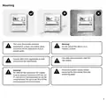
- Page 8: Mounting The room thermostat must be mounted in a clean, dry indoor place and must not be exposed to drip or splash water. Do not mount the device on a metallic surface. Use only valve actuators rated for 100-240VAC. Comply with local regulations to wire and protect the thermostat. Disconnect power supply before removing the thermostat from the mounting plate. No internal line protection for supply lines to external consumers (Q1, Q2, Q3, V1 and V2). It is recommended to use 6A circuit breaker for each one. Risk of fire and injury due to short-circuits.
- Page 9: Do not mount on a wall in niches or bookshelves, behind curtains, above or near heat sources, or exposed to direct solar radiation. Mount about 1.5 m (5 feet) above the floor. Adapt the line diameters as per local regulations to the rated value of the installed overcurrent protection device. Inputs IO1 and IO2 carry mains potential. If the sensor’s cables are extended, they must be suited for mains voltage. The 100-240VAC mains line must have a circuit breaker with a rated current of no more than 10 A. Properly size the cables to the thermostat, fan and valve actuators for 100-240VAC mains voltage.
- Page 10: Turn off the power supply to the existing thermostat and remove the thermostat without disconnecting the cables. Find out what is the correct wiring diagram. Further in this document, you’ll find wiring diagrams for different types of Fan Coil Units, compatible with the Fan Coil Thermostat. You have to determine which wiring diagram your FCU is using and later wire the terminals accordingly. Correctly identifying the wiring diagram is of paramount importance for the correct working of the Fan Coil Thermostat. Remove the power module from the Fan Coil Thermostat by lifting it. You can use a flat screwdriver to remove it. When connecting any wires to the FCT terminals, please do not leave any stranded wires or exposed wire metal not fully in the terminal.
- Page 11: Connect the wires according to the chosen wiring diagram in Step 2. Re-insert the power module into the FCT and restore the power using the breaker. Enter the Installer’s menu by turning the device off first, then hold the reset button and the fan speed button for 5 seconds. Check the connections every 6 months and tighten them again if needed.
- Page 12: Do not use non-flat head screws for the mounting. Once you enter the Installer’s menu, select the correct wiring diagram for your application. Validate that the Fan Coil Unit is reacting to adjusting the modes, fan speed and target temperature through the FCT. Slide the FCT on the mounting bracket and tighten the security screw on the bottom. Mount the mounting bracket on the wall using the enclosed screws and if needed - dowels.
- Page 13: User interface guide The device has 4 visible physical buttons.
- Page 14: Button functions include ON/OFF/MODE, down arrow, up arrow, and fan. A short press of the ON/OFF/MODE button turns the thermostat ON when it is OFF. When the device is ON, a short press changes between operational modes such as heating, cooling, and ventilation. A long press of 3 seconds turns the thermostat OFF. The down arrow decreases the target temperature and navigates items in the Installer’s menu. The up arrow increases the target temperature and also navigates items in the Installer’s menu. The fan button changes the fan speed according to the allowed fan speeds.
- Page 15: The device has a simple and intuitive user interface. Assembled MClimate Fan Coil Thermostat. LoRaWAN®, top view.
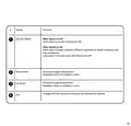
- Page 16: Section meaning modes selection shows the current selected operational mode - heating/cooling/ventilation. Current temperature indicates the current temperature measured in the room. Humidity indicates the current relative humidity measured in the room. Target temperature shows the current target temperature of the thermostat. Fan speed shows the selected fan speed. Occupancy indicates occupied/not occupied status, determined by an additional sensor or set through a downlink. LoRaWAN signal indicates the current spreading factor. Valve status indicates if any of the valves are currently open or closed. Messages display various statuses indicating the radio activity of the device. Filter alarm shows in case a filter alarm is connected to the IO1 and IO2 terminals.
- Page 17: Operating instructions Temperature adjustment Use the up and down button to adjust the target temperature. The target temperature cannot be adjusted while in ventilation mode. If you want to change the step of increase/decrease of the target temperature, you can further configure it via a downlink.
- Page 18: Turning the thermostat ON/OFF The button on the far left of the thermostat serves two functions - turn it on and off and switch between modes. If the thermostat is currently off (screen is blank), a short press of the ON/OFF/MODE button will turn it on. The device should show more information, including measured temperature & relative humidity, fan speed, and target temperature if the selected mode is heating or cooling. If you want to turn the thermostat OFF, hold the ON/OFF/MODE button for 3 seconds.
- Page 19: Fan speed can be changed by clicking the FAN button. You can adjust the fan speed according to the allowed speeds in your wiring diagram. ECM fans have six available speeds. A downlink can be used to limit the selection of fan speeds. You can restrict the options to only the first and second speeds.
- Page 20: Mode selection The device supports three operating modes: heating, cooling, and ventilation. Some modes might be disabled based on the wiring diagram of the Fan Coil Unit. A 2-pipe fan coil unit can either heat or cool, but not both throughout the year. Short-pressing the ON/OFF/MODE button switches between heating/ventilation or cooling/ventilation. The allowed operational modes depend on the current configuration of the system. If using a 10k NTC connected to IO1 and IO2, the FCT determines allowed operational modes based on water circulation.
- Page 21: Connectivity and smart building features LoRaWAN Class C enables devices to constantly listen for commands from the gateways. The device will send information only on the keepalive interval or any change in the target temp/mode/fan speed selection occurs. Unlike Class A devices, the FCT is able to receive commands from the Application/Network server in real-time. The device is compatible with MClimate Enterprise, which unlocks monitoring and controlling capabilities using MClimate devices. For further instructions on how to add your MClimate FCT to the Enterprise, please refer to the available documentation. Integration with Building Management Systems (BMS) and Building Automation Systems (BAS) is possible with a special gateway. This gateway translates the signal from LoRaWAN and exposes the device’s points as Modbus or BACnet objects for further processing. Refer to our website for up-to-date information on available LoRaWAN <> BMS gateways.
- Page 22: Wiring diagrams Heating and cooling with 3-speed fan 2-pipe ON/OFF (220VAC) 1-3 speeds fan 2-pipe ON/OFF 3-wire valve (220VAC) Multipurpose input/output (occupancy, auto change-over, etc.) 4-pipe ON/OFF (220VAC) 1-3 speeds fan
- Page 23: Heating and cooling with ECM fan 4-pipe ON/OFF (220VAC) 2-pipe ON/OFF (220VAC) 2-pipe 3-wire ON/OFF (220VAC)
- Page 24: Page 24

Wengart TP808-3 Heat Pump Thermostat User Guide

HIVE SLT3 Thermostat User Guide

Honeywell FocusPRO 5000 Series Digital Thermostat User Guide

Honeywell evohome Smart Thermostat User Guide

LG PREMTA200 Deluxe Thermostat User Guide

GENERAL SOLARA 330S SMART Smart Room Thermostat User Manual

ENSTO ECO10BTW-J Heat Control Thermostat Instruction Manual

SALUS RT310i Internet Thermostat Installation Guide

VIMAR 02913 Surface LTE Thermostat Installation Guide

king K702E-2 SimplStat Electronic Thermostat Instruction Manual