
Home > EPH CONTROLS > EPH Controls RFCP-RFCA RF Cylinder Thermostat Instruction Manual
EPH Controls RFCP-RFCA RF Cylinder Thermostat Instruction Manual
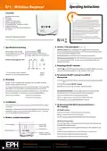


Page 1 of 1
Operating Instructions
RF1 - Wireless Receiver
Contents
1. Specifications & wiring
2. Mounting
3. Installation
4. Button / LED description
5. Resetting the RF1 receiver
6. To connect the RF1 receiver to a RFCA
wireless thermostat
CAUTION!
Before commencing any work on the electrical
connections, you must first disconnect the device from
the mains. None of the 230V connections must be live
until the installation has been completed and the housing
is closed. Only qualified electricians or authorised service
staff are permitted to open the terminal box.
7. To disconnect the RFCA thermostat from a
RF1 receiver
There are parts that carry mains voltage behind the cover.
The terminal box must not be left unsupervised when
open. (Prevent non specialists and especially children
from gaining access to it.)
Ensure that this wireless enabled receiver is installed 1
metre from any metalic object, television, radio or wireless
internet transmitter.
Important: Keep this document
Prior to operation, it is neccessary to complete all required settings described in this section.
4. Button / LED description (Continued)
1. Specifications & wiring
Wireless connect: Once voltage has been applied this button may be
pressed to initialise the pairing process with the wireless thermostat. Once
pressed the red LED will begin to flash.
Power Supply: 230 Vac 50Hz
Contact Rating: 250 Vac 10(3)A
Ambient Temp: 0~50°C
Class II appliance
Pollution degree 2: Resistance to
voltage surge 2500V; as per EN 60730
Manual override: This button will manually override the system.
Wireless connect indicator: This LED will flash on receiving wireless signals.
If it is constantly ON, the RF1 receiver has been disconnected from the
wireless thermostat.
Internal wiring diagram for RF1
3
2
1
L
L
N
N
5. Resetting the RF1 receiver
COM
ON
OFF
RESET
Press the
button located on the side of the receiver. Within 2 seconds,
press press the connect button. The RF1 receiver is now reset.
* If mains voltage output is required,
MAINS
SUPPLY
terminals L & 2 must be electrically linked.
6. To connect the RF1 receiver to a RFCA
thermostat
2. Mounting
The wireless connect LED will be constant red once power has been applied.
The RF1 receiver should be wall mounted in an area within 20 metres
distance of the wireless thermostat.
Press the
button on the RF1 receiver.
Connect
Both the red and green LED on the RF1 will begin to flash.
It is important that the receiver is mounted more than 1 metre away from
metal objects as this will affect communication with the thermostat.
The receiver should also be installed at least 1metre from any electronic
devices such as radio, TV, microwave or wireless network adaptor.
On the RFCA thermostat, press the
button on the bottom of the
thermostat, the front housing will detach from the baseplate.
The unit can be fitted to:
1. Recessed conduit boxes
2. Surface mounting boxes
Press the CODE button on the printed circuit board.
When r1 appears on the screen, press the hand wheel once.
The thermostat is now connected to the RF1 receiver.
3. Installation
7. To disconnect the RFCA thermostat from a
RF1 receiver
Slacken the fastening screw on the bottom of the receiver with a philips
screwdriver.
The receiver is hinged and can be opened 180 degrees. Mount the unit as
described in section 2. Wire the unit as described in section 1. Close the
receiver and tighten the fastening screw.
On the RF1 receiver
Press the reset button on the right side of the housing.
Within 2 seconds, press the connect button.
The RF1 receiver is now disconnected from the RFCA thermostat.
4. Button / symbol description
On the RFCA thermostat
Press the
button on the bottom of the thermostat, the front housing
System ON
(Green LED)
Connect button
Manual override
will detach from the baseplate.
Press the RESET button on the printed circuit board. “NO”will flash on the
screen.
Reset button
Rotate the hand wheel clockwise until “YES”appears on the screen.
Press the hand wheel once to confirm the setting.
Wireless connect
indicator (Red LED)
The thermostat is now disconnected to the receiver.
EPH Controls Ireland
EPH Controls UK
20221103_RF1(RFCP/RFCA)_OpIns_PK


| General | Details |
|---|---|
| Name | EPH Controls RFCP-RFCA RF Cylinder Thermostat Instruction Manual |
| Make | EPH CONTROLS |
| Language | English |
| Filetype | PDF (Download) |
| File size | 0.1 MB |
 (1 votes, average: 5.00 out of 5)
 Loading...

EPH CONTROLS eTRV-HW Smart Cylinder Thermostat User Guide

EPH CONTROLS eTRV-HW Smart Hot Water Thermostat Instruction Manual

EPH CONTROLS eTRV Smart Radiator Thermostat Instruction Manual

EPH CONTROLS 20221026 RFRA – RF Room Thermostat Instruction Manual

EPH CONTROLS CDTP2 Hardwired Room Thermostat Instruction Manual

EPH Controls CDT2-24 24V Room Thermostat Installation Guide

EPH CONTROLS RFCA RF Cylinder Thermostat Instruction Manual

EPH CONTROLS PR092K7 RF Cylinder Thermostat Instruction Manual

EPH CONTROLS COMBIPACK2 Smart Thermostat with Automation and Optimum Start Instructions

EPH CONTROLS CDC2 Cylinder Room Thermostat User Guide

EPH Controls RFCP-RFCA Manual: Questions and Answers
What is the power supply specification for EPH Controls RFCP-RFCA?
230 Vac 50Hz, Class II appliance. Instruction Manual, p. 1
What do terminals L, N and 2 on the EPH Controls RFCP-RFCA receiver do?
L and N connect to mains power. Terminals L and 2 must be electrically linked if mains voltage output is required.
| Terminal | Function |
|---|---|
| L | Live mains connection |
| N | Neutral mains connection |
| 2 | Output terminal, link to L for mains voltage output |
Can I install a wireless receiver less than one metre away from metal objects or electronics?
No. The receiver must be installed more than 1 metre away from metal objects and at least 1 metre from electronic devices such as radio, TV, microwave or wireless network adaptor, as this affects communication. Instruction Manual, p. 1
Where is the reset button located on the EPH Controls RFCP-RFCA?
On the right side of the housing. Instruction Manual, p. 1
More EPH Controls thermostat manuals

GENERAL SENNA 300 Digital Room Thermostat User Manual

Olympia BS-812-P Programmable Thermostat User Manual

Honywell UtilityPRO Series Thermostat User Manual

TRU COMPONENTS TC-NTL-ExT6 Hazardous Area Thermostat Instructions

Honeywell TH5000 Series FocusPRO Non-Programmable Digital Thermostat Installation Guide
EPH CONTROLS CDC2 Cylinder Room Thermostat User Guide

Danfoss RA2000 TRV Thermostat Instructions

ADAX VG11 Digital Thermostat User Guide

GREYSTONE TLGLF24X01 Glass Low Limit Thermostat Instruction Manual

UNDERFLOOR HEATING WORLD UT5 Touch Screen Thermostat Instruction Manual