
Home > ENGO CONTROLS > ENGO CONTROLS FAN-24W 24V Fan Coil Thermostat User Guide
ENGO CONTROLS FAN-24W 24V Fan Coil Thermostat User Guide
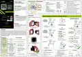


Installation of the Wi-Fi thermostat in the app
Make sure your router is within range of your smartphone. Make sure you are connected to the Internet. This
will reduce the pairing time of the device.
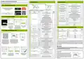
Installer parameters
Installer parameters
To enter installer parameters press and hold button for 3 seconds.
2
Histeresis for cooling valve
(ON-OFF -> 24 V output for actuator)
P20
0,1°C -2°C
Hysteresis value for the COOLING valve
1°C
2°C
1
AUTO
STEP 1 - DOWNLOAD ENGO SMART APP
AUTO
The value of the difference between the set temperature and the
0,5°C - 5°C temperature of the room so that the controller automatically changes
the Heating/cooling operations
Heat Cool switching
- Dead zone for 4-pipe system
P21
P22
Powered By
Download the ENGO Smart app from Google
Play or Apple App Store and install
3 sec.
In a 2-pipe system, below this value the
system switches to cooling mode and 10°C -25°C
allows the fan to start
In a 2-pipe system, below this value the system switches to
cooling mode and allows the fan to start
10°C
30°C
it on your smartphone.
Use or button to move between parameters. Enter the parameter by . Edit the parameter using
or . Confirm the new parameter value with the button.
In a 2-pipe system, above this value the
P23 system switches to heating mode and 27°C -40°C
allows the fan to start
In a 2-pipe system, above this value the system switches to
heating mode and allows the fan to start
GET IT ON
Default
value
-
Pxx
Function
Value
Description
Preview of the current controller configuration
None connected
Parameter used in 4-pipe systems with automatic switching between
heating and Cooling.
ConF
Read-only parameter
-
P24
P25
Cooling mode switching ON delay
Maximum floor temperature
0-15 min.
5°C - 45°C
0 min.
35°C
Available on the
This avoids switching between modes too often
heating and cooling as well as room temperature oscillations
0
In order to protect the floor, cooling will be switched on, when
the temperature of the floor sensor exceeds the maximum value
Input used to change heating/cooling via contact
external connected to S1-COM:
- S1-COM open--> HEAT mode
1
2
In order to protect the floor, cooling will be turned off, when the
temperature of the floor sensor drops below the minimum value
STEP 2 - REGISTER THE NEW ACCOUNT
P26
P27
P28
Minimum floor temperature
Backlight brightness
5°C - 45°C
10°C
30%
NO
- S1-COM short-circuited--> COOLING mode
Input used for AUTOMATIC heating/cooling change
based on the PIPE TEMPERATURE in a 2-pipe system.
The controller switches between heating and cooling modes to
pipe temperature set in parameters P23 and P24.
0% - 100%
Adjustable in the range from 10 to 100%
To register a new account, please follow the steps below:
P01
S1 - COM input configuration
0
NO
PIN
NO
Function disabled
PIN Code for installer parameters
1
2
3
4
Function enabled
Fan operation permit dependent on temperature measurement
on the pipe. E.g. if the temperature on the pipe is too low and the
regulator is in heating mode - the pipe sensor will not allow you to
start fan. The change of heating/cooling is done manually - using the
buttons. Values for fan control based on pipe temperatures are set in
parameters P23 and P24.
NO
Require a PIN to unlock the keys every
time (function active when P29=PIN)
P29
FAN
CLR
NO
YES
NO
YES
YES
3
NO
Inactive - the output contacts for fan control are completely disabled
Fan
YES
NO
Enabled
No action
4
0
Activating the Floor Sensor in the UFH configuration
None connected
Clear settings factory reset
YES
Factory reset
1
When the contacts are open switch on Eco Mode
P02
P03
S2 - COM input configuration
Display temp accuracy
0
Click„Sign Up”to create Enter your e-mail Enter the verification code Then set the login
new account. address to which received in the email. password.
the verification code Remember that you only have
2
External temperature sensor
Installer parameters - RS-485 communication settings
0,1°C
0,5°C
Indication of room temperature with an accuracy of 0,1°C
Indication of room temperature with an accuracy of 0,5°C
0,1°C
will be sent. 60 seconds to enter the code!
Default
value
-3.0°C to
+3.0°C
If the thermostat indicates wrong temperature,
you can correct it by max 3.0°C
Pxx
Function
Value
Description
P04
P05
P06
Offset temperature
0°C
35°C
5°C
STEP 3 - CONNECT THE THERMOSTAT TO WI-FI
Addr
MODBUS Slave device address (ID).
1 - 247
4800
MODBUS Slave Address (ID)
1
Maximum temperature setpoint
Minimum temperature setpoint
5°C - 45°C
5°C - 45°C
Maximum heating / cooling temperature that can be set
Minimum heating / cooling temperature that can be set
After installing the app and creating an account:
9600
BAUD
Bitrate (Baud)
Bitrate (Baud)
9600
19200
38400
None
1
2
3
NO
Function disabled
Function enabled
P07
ECO mode
NO
YES
Lack
Parity bit
- sets data parity for error detection
P08
P09
ECO temp value in HEAT mode
ECO temp value in COOL mode
5°C - 45°C
5°C - 45°C
ECO temp value in HEAT mode
ECO temp value in COOL mode
15°C
30°C
PARI
None
1
Even
Odd
1
Even
Odd
1stop bit
STOP
Stop bit
2
2 stop bit
This parameter allows you to specify the minimum fan speed. Gradually
increase the setting until the fan starts to run and accept/save the
parameter value.
0% ... max
(0 - 10V)
P10
P11
MInimum fan speed
Maximum fan speed
10%
90%
Modbus RTU features 8-bit data coding.
On your mobile device, make sure Make sure the thermostat is powered
In the app, select:
„Add Device”.
This parameter allows you to define the maximum fan speed. We
increase the speed and if we see that the speed no longer increases
despite the setting, we accept/save the parameter value.
the ENGO Smart has access to
permissions (Location, Bluetooth,
Nearby devices). Then turn on
on and configured. Then press and
hold the buttons on the thermostat
for approx. 3 seconds until the display
min... 100%
(0-10V)
The MODBUS RTU structure uses a master-slave system to exchange messages. It allows the connection of maximum
of 247 slaves, but only one master. The master controls the operation of the network and only it sends the request. The
slaves do not undertake the transmission themselves. Each communication starts with making a request by the master
to the slave, which responds to the master with what it has been asked. The master (computer) communicates with the
slaves (controllers) in two-wire RS-485 mode.For this purpose data exchange uses data lines A+ and B-, which MUST
be one twisted pair .
0...100% Fan speed in gear I (value depends on P10 minimum speed range and
(0-10V) P11 maximum speed)
0...100% Fan speed in gear II (value depends on P10 minimum speed range and
(0-10V) P11 maximum speed)
0...100% Fan speed in gear III (value depends on P10 minimum speed range and
Bluetooth and Location. Connect to shows„PA”. Then release the keys. The
2.4GHz Wi-Fi network to which you
want to assign the device.
P12
P13
P14
P15
Fan speed I gear in manual mode
Fan speed II gear in manual mode
Fan speed III gear in manual mode
30%
60%
90%
0,5°C
pairing mode will be started up.
(0-10V)
P11 maximum speed)
The fan will start operating if the room temperature drops below
the set temperature by the value of parameter
WARNING:
Fan ON temperature in heating mode 0°C - 5°C
4
5
6
8
Before the controller is connected to the RS-485 network, it must first be correctly configured.
Communication parameters and descriptions of MOD-BUS registers are available in the appendix
Fan speed range in automatic speed
Fan speed range in automatic fan speed mode
(for heating and cooling)
P16
0°C - 10°C
mode
2°C
This parameter is responsible for the 0-10 V modulated output of the
valve.
Δ temp. for heating and cooling valve
output
- In heating mode: If the room temperature drops, the valve opens in
proportion to the delta.
- In cooling mode: If the room temperature rises, the valve opens in
proportion to the size of the delta.
The opening of the valve starts from the room setpoint temperature.
P17
0,1°C -2°C
1°C
Factory reset
To RESET controller to factory settings, hold down the
&
Name the device
and click„Done”.
After finding the
thermostat, go„Add”.
Select the Wi-Fi network
in which the thermostat
will operate and enter the
password of this network.
The thermostat has been
installed and displays the
main interface.
buttons until the FA message appears. Then release the keys.
Controller will restart, restore default factory settings and displays
the home screen. The device will be also removed from app.
Factory reset can be done within 5 minutes after power supply
connection. If controller is connected longer - factory reset cannot
be performed.
Histeresis for HEATING valve
(ON-OFF -> 24 V output for actuator)
P18
P19
0,1°C -2°C
Hysteresis value for the heating valve
1°C
The fan will start operating if the room temperature
rises above the set temperature by the value of parameter
Fan ON temperature in cooling mode 0°C - 5°C
0,5°C

| General | Details |
|---|---|
| Name | ENGO CONTROLS FAN-24W 24V Fan Coil Thermostat User Guide |
| Make | ENGO CONTROLS |
| Language | English |
| Filetype | PDF (Download) |
| File size | 0.4 MB |
 (1 votes, average: 5.00 out of 5)
 Loading...

ENGO Controls EONE230W Internet Controlled Thermostat User Guide

ENGO CONTROLS EFAN-230W Fan Coil Thermostat User Guide

ENGO CONTROLS EASY230W Non-Programmable Wired Thermostat User Guide

ENGO CONTROLS EONE230 Internet Controlled Thermostat User Guide

ENGO CONTROLS EONEBATW, EONEBATB Internet Controlled Thermostat User Manual

ENGO Controls E901WIFI Internet Wireless Thermostat User Guide

ENGO CONTROLS EONE-BATW, EONE-BATB Internet Controlled Thermostat User Guide

ENGO CONTROLS EFAN-24W Fan Coil Thermostat User Guide

ENGO CONTROLS EFAN-230W WIFI 230V Fan Coil Thermostat User Guide

ENGO CONTROLS E10-MBUSW, E10-MBUSB Wi-Fi MODBUS Thermostat User Guide


Innova B3V151 Electronic Thermostat User Manual

GENERAL LIFE FH252S Underfloor Heating Thermostat User Manual

nVent RAYCHEM ETS-05 Electronic Thermostat Instruction Manual

Honeywell CT87A Round Thermostat Instruction Manual

tekmar TEK564 Invita WiFi Thermostat User Manual

VIMAR 02913 Surface LTE Thermostat Installation Guide

BEOK TDS72 Digital Screen Thermostat Instruction Manual

Munters RDT-5 Triple Phase Digital Thermostat User Manual

Lightwave DTS92E Honeywell Home Wireless Room Thermostat User Manual

GENERAL LIFE MITRA 250S Digital Room Thermostat User Manual