Munters RDT-5 Triple Phase Digital Thermostat User Manual


RDT-5
Manual for use and maintenance
RDT-5
Triple Phase Digital Thermostat
Ag/MIS/UmGB-2479-07/17 Rev 1.3
P/N: 116343

| General | Details |
|---|---|
| Name | Munters RDT-5 Triple Phase Digital Thermostat User Manual |
| Make | Munters |
| Language | English |
| Filetype | PDF (Download) |
| File size | 0.5 MB |


Munters RDT-5 Triple Phase Digital Thermostat User Manual Overview
Summary of Contents
- Page 1: Manual for use and maintenance Triple phase digital thermostat
- Page 2: RDT-5 manual for use and maintenance. This manual is an integral part of the apparatus along with the attached technical documentation. The document is intended for the user of the apparatus and cannot be reproduced without prior authorization. Munters reserves the right to modify the apparatus in accordance with technical and legal developments. © Munters AB, 2021.
- Page 3: Introduction Munters reserves the right to make alterations to specifications, quantities, dimensions, etc. The information contained herein has been prepared by qualified experts within Munters. While we believe the information is accurate and complete, we make no warranty or representation for any particular purposes. Congratulations on your excellent choice of purchasing a RDT-5! It is important that it is installed, commissioned, and operated correctly. Before installation or using the thermostat, this manual should be studied carefully. The manual is intended as a reference for installation, commissioning, and day-to-day operation of the Munters Controllers. Munters cannot guarantee to inform users about the changes or to distribute new manuals to them. No part of this manual may be reproduced in any manner whatsoever without the expressed written permission of Munters. The contents of this manual are subject to change without notice.
- Page 4: Precautions Always connect temperature and sensor shields to earth ground. Avoid mixing high voltage wiring with sensor and low voltage wiring. Keep the controller as far as possible from heavy contactor boxes and other sources of electrical interference. Only a trained installer may install this unit, in accordance with the local National Electrical Codes. Introduction to the RDT-5 The Triple Phase RDT-5 is a five stage digital thermostat that works in conjunction with controllers. The RDT-5 works as a stand-alone unit, using its own temperature to activate the backup system. Digital thermostats provide highly accurate readings, ensuring that both the Platinum Controller function according to specifications.
- Page 5: Features include five independent thermostats and the ability to set each stage for backup cooling or heating operations. The system supports a 10-point temperature curve and can function as a standalone unit or with Platinum. It displays stage temperature, state, and system information. Alarm logic is in place to detect failures, and the unit comes with built-in power and input protection. No software is needed to run the unit; it is only required for configuration. The LED indicators provide information on system status, including operational thermostats and power source status. The System OK and Check System LEDs cannot be lit simultaneously.
- Page 6: Display shows different abbreviations. The following table explains these abbreviations. Table 2: RDT-5 Abbreviations. Temperature differential refers to the temperature difference between the temperature curve and the required temperature to operate coolers or heaters. Abbreviations include terms for days, temperatures, modes, and units of measurement. Standalone mode and platinum mode are specific operational modes. Centigrade and Fahrenheit are temperature measurement units. Current growth day and hour are time-related measurements. Minute is also a time-related measurement. The document includes a copyright notice from Munters AB, 2021.
- Page 7: Using the RDT-5 The following sections describe how to use the RDT-5. RDT-5 keyboard Use the Stage key to navigate between the stages. The current stage is always displayed in the one digit window. Use the Select key to display the current temperature and set the target temperatures. Use the Down key to decrease parameter settings and set the temperature curve. Use the Up key to increase parameter settings and set the RDT-5 parameters.
- Page 8: Cold Start returns the unit to its default settings. Only perform this procedure when advised to do so by your dealer or a Munters technician. To perform a Cold Start, disconnect power, apply power while pressing Select, Up Arrow, and Down Arrow, and press Select when the Cold Start Screen appears. After applying power, RDT-5 loads the temperature and growth day settings and displays the software version on the screen for a few seconds. If the RDT-5 cannot load the settings, it displays ----- in place of the software version. RDT-5 retains all settings in the event of any power cut. The following sections explain how to configure the RDT-5. This section describes the basic setup steps. For more detailed information refer to the subsequent sections. Press Select quickly to display the current temperature. Press Down Arrow for three seconds to set the general settings. Press Select for three seconds to show the current stage activation temperature and modify the dif using the arrow keys.
- Page 9: Press Up Arrow for three seconds to set the day. The RDT-5 Main Screen displays the current stage and target temperature. To navigate between stages, press the Stage key. To display the current temperature, press Select quickly. After 10 seconds of inactivity, the display returns to the Main Screen. There are several parameter settings that must be set before configuring target temperatures. The RDT-5 can work in standalone mode or in conjunction with the Platinum controller. To set the basic settings, press Down Arrow for three seconds. Use the arrow keys to select PrE or Aut. Set the current day and hour using the arrow keys and press Select.
- Page 10: Press Select to access the current minutes value. Use the arrow keys to set the minutes. Values are saved to memory, and the display returns to the Main Screen. The stage activation temperature determines when cooling and heating operations take place. RDT-5 enables setting a separate stage activation temperature for each stage. To set the stage activation temperature, press Select for three seconds. Using the arrow keys, modify the parameter and press Stage to switch to the next stage. Values are saved to memory, and the display returns to the Main Screen. RDT-5 Version 1.0.2 enables setting a temperature curve consisting of 10 lines. To configure the temperature curve, press Up Arrow for three seconds.
- Page 11: Press the arrow keys to set the day (Range: 1 to 300). The screen displays P (curve point) and a number (the target temperature). Use the arrow keys to set that day's target temperature (Range: 0.5 to 50 C). Entering a zero for a day value deletes the day and the temperature. Even when connected to a controller, these settings are saved in the RDT-5 only. Platinum Version 5.10 (and higher) supports defining the temperature curve using Platinum software. After 60 seconds of keyboard inactivity, the display automatically returns to the Main Screen. Users employing Version 1.0.1, refer to Appendix A: Setting the Temperature Curve In Legacy Software. Values are saved to memory. When you complete line 10, the display returns to the Main Screen.
- Page 12: Installation procedures are detailed in the following sections. The RDT-5 must be installed by an authorized electrician. Disconnect the power to avoid electrical shock and damage during installation. It is recommended to install the unit in the service room to avoid exposure to harmful gases or high humidity. The power supply to the controller should be protected by a 5 Amps circuit breaker. Mount the RDT-5 vertically on the wall using the four supplied screws. To open the enclosure, unclip the two left-side clips in the front. Connect the wires according to the wiring diagrams detailed in the next section. The following sections detail the RDT-5 wiring. Refer to specific pages for selecting heating or cooling functions, powering the RDT-5, and alarm wiring.
- Page 13: Each relay must be set to operate a heater or cooler. To set the relay function: On each relay, place the jumper over the required pins. Figure 5 shows jumper locations. Figure 6 displays two examples.
- Page 14: There is no text on the page to extract.
- Page 15: Ensure that each temperature sensor is installed correctly in the required location. If a 30 Kohm resistor is installed in place of a temperature sensor, the stage is non-operational. To enable stage operation, remove the resistor and install a sensor. Any stage having neither a sensor nor a resistor causes an alarm (Sensor Failure Event). Powering the RDT-5.
- Page 16: Caution: When powering the RDT-5, the L1, L2, and L3 ports must be fed from different power sources, phases, or breakers. An alarm is triggered when either the primary or secondary power source fails, a sensor is shorted or fails to operate, or the CPU fails. Even if the CPU ceases to operate, the RDT-5 continues to function. The CPU does not run the unit; it is used only to enter the unit parameters. The RDT-5 can be wired directly to the Platinum’s digital input card. In this configuration, the RDT-5 can provide two functions: transmitting an alarm to a PC in the event of a power or sensor failure and functioning when the Platinum has a problem with its relays, breakers, or sensors. The Platinum transmits an alarm when RDT-5 activates one of the stages. Both functions are optional, but wiring the RDT-5 to Platinum Controllers is strongly recommended.
- Page 17: Wiring the backup alarm ports to the Platinum digital input card.
- Page 18: Platinum 5.10 and above support RS-485 communication with the RDT-5. All Platinum versions support RS-232 communication with the RDT-5. When using RS-232 cabling, place the RDT-5 within 10 meters of the controller. The RS-232 Communication Card comes prewired to the RDT-5 Alarm NO and COM ports. When wiring the RDT-5 to a Digital Card (RDIC), leave this wiring in place and connect RDIC wiring to the same ports. If your RDT-5 is equipped with a C-RNET-DIR Ver 1.0.0 communication card, contact your dealer about an upgrade.
- Page 19: Page 19
- Page 20: Caution: To ensure effective signal transmission, install a 120 ohm resistor between ports A and B on both the RDT-5 Communication Card and the Platinum RS-485 Communication Card. Configuring the RS-485 communication consists of defining the 5V status, defining the termination, and defining the baud rate. Always enable 5V in the RDT-5. Termination is required in each chain, at the beginning and end units. When RDT-5 is a beginning or end unit, enable 120 ohm termination using the S2 dipswitch. 115k bit/sec speed is always on.
- Page 21: RDT-5 at Chain endpoint: Termination, (5V), Baud Rate RDT-5 in Mid Chain: Termination, (5V), Baud Rate Figure 16: RDT-5 at Chain Endpoint Figure 17: RDT-5 in Middle
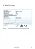
- Page 22: Specifications Power supply Mains voltage primary Triple phase, 115 VAC Main fuse primary 5 A Maximum power consumption Available power for peripheral equipment Operating temperature range CAUTION RDT-5 ceases to operate outside of the operating temperature range.
- Page 23: Appendix A: Setting the temperature curve in legacy software RDT-5 enables setting a three point/three day temperature curve. To configure the temperature curve, press the up arrow for three seconds. The three digits display F.d and 1 (Stage 1). Use the arrow keys to set the day and press select. The three digits display F.t and the current curve setting. Values are saved to memory. The display returns to the main screen. After 60 seconds of inactivity on the keyboard, the display automatically returns to the main screen.
- Page 24: Warranty and technical assistance Munters products are designed and built to provide reliable and satisfactory performance but cannot be guaranteed free of faults. The user must take into account the possibility of unforeseeable defects and arrange adequate emergency or alarm systems. Munters extends this limited warranty to the first purchaser for one year from the date of delivery. The warranty does not apply if the products have been repaired without express authorization from Munters. The user accepts total responsibility for incorrect use of the products. Claims for defects must be made in writing within eight days of discovery and within 12 months of delivery. Munters has thirty days from receipt to take action and may examine the product at the customer’s premises. Munters has the option of replacing or repairing defective products free of charge. Munters will not be liable for costs incurred in demounting defective parts or associated travel costs. Munters reserves the right to alter specifications in this manual without prior notice.
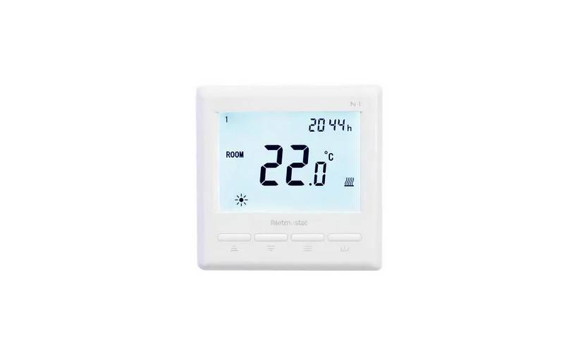
Netmostat N-1 Smart Wifi Programmable Thermostat User Manual

Honeywell CT87N The Round Non Programmable Thermostat Owner’s Manual

STELPRO ST402PFF Programmable Electronic Thermostat Owner’s Manual

WARMZONE BR1015A07 WZ Touch Thermostat User Guide

Network Thermostat X5-WIFI Smart Touchscreen Thermostat Instruction Manual

Tempio Controls HY02B05 WIFI Digital Heating Thermostat User Manual

FRICO TD10 Electronic Thermostat Instructions

SIEMENS TH192 HC Heating-Cooling Room Thermostat Instruction Manual

EBECO EB-25 Regulator Thermostat Instruction Manual
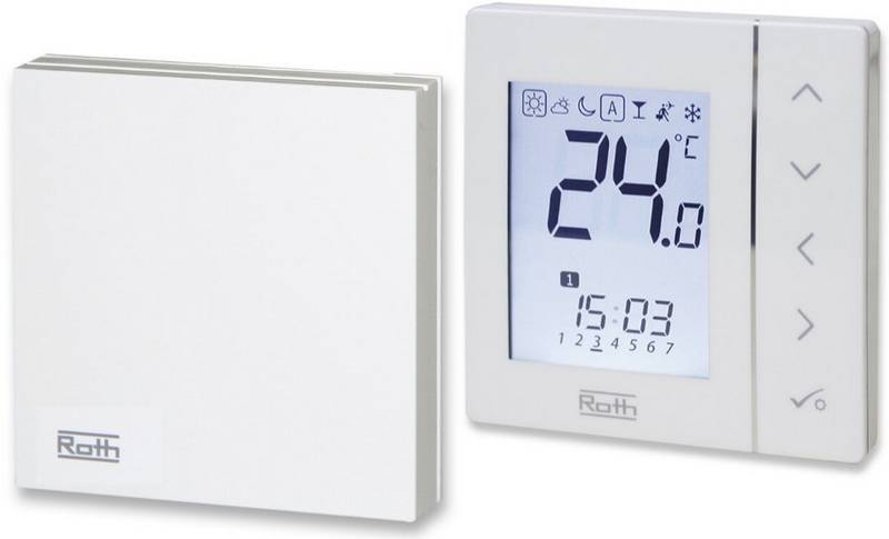
Roth Basicline Wired Thermostat Installation Guide