Honeywell CT87A Round Thermostat Instruction Manual


®
CT87A,B,J Round Thermostat
LOW VOLTAGE (15 TO 30 VAC),
THERMOSTAT AND MOUNTING HARDWARE
Installation Instructions
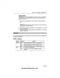
Verify that you have the
correct thermostat
1
Using the compatibility chart
below, verify that you purchased
the correct CT87Thermostat for
your heating/cooling system. If
you are unsure which model is
right for your system, visit
yourhome or call Honeywell
Customer Care at
1-800-468-1502.
Compatible with:
Heating/Cooling system
CT87A CT87B CT87J
Heating only: Gas or oil fueled warm air, steam, or hot Yes
Yes
No
water heat
Cooling only: Electric air conditioning
Yes*
No
Yes
Yes
Yes
No
Heating and cooling: Gas or oil fueled warm air,
steam, or hot water heat with electric air conditioning
Single stage heat pump: Outdoor heating/cooling unit No
No
Yes
(compressor) with no auxiliary or backup heat.
Electric heat furnace with or without cooling:
No
No
No
Yes
No
Electric baseboard: Electric heating strips located just No
above the floor, usually 120-240 volts
Multistage: A conventional system with more than one No
stage, or an outdoor heating/cooling unit (compressor)
with auxiliary or backup heat.
No
No
* CT87A is compatible with 2-wire cooling-only systems.
® U.S. Registered Trademark
Copyright © 2002 Honeywell
All Rights Reserved
69-0274-6
firealarmresources.com

| General | Details |
|---|---|
| Name | Honeywell CT87A Round Thermostat Instruction Manual |
| Make | Honeywell |
| Language | English |
| Filetype | PDF (Download) |
| File size | 0.29 MB |


Honeywell T6 Pro Programmable Thermostat User Manual

Honeywell D1-528 Direct Thermostat Installation Guide

Honeywell FocusPRO P200 Programmable Thermostat User Guide

Honeywell RCHT8610WF Series Smart Thermostat Installation Guide

Honeywell T9 Smart Thermostat Installation Guide

Honeywell TH2320WF4011 FocusPRO Smart S200 Series Thermostat User Guide

Honeywell TL116A Thermostat Installation Guide

T10 Pro Smart Thermostat with Redlink Room Sensor

Honeywell TH6320WF2003 Lyric T6 Pro Wi-Fi Programmable Thermostat User Guide

Honeywell Lyric T5 Wi-Fi Thermostat Installation Guide

Honeywell CT87A Round Thermostat Instruction Manual Overview
Summary of Contents
- Page 1: CT87A,B,J round thermostat Low voltage (15 to 30 VAC), thermostat and mounting hardware Installation instructions Verify that you have the correct thermostat Using the compatibility chart, verify that you purchased the correct CT87 thermostat for your heating/cooling system Compatible with heating/cooling systems Heating only: gas or oil fueled warm air, steam, or hot water heat Cooling only: electric air conditioning Heating and cooling: gas or oil fueled warm air, steam, or hot water heat with electric air conditioning Single stage heat pump: outdoor heating/cooling unit with no auxiliary or backup heat
- Page 2: CT87A,B,J round thermostat Carefully unpack your new thermostat; rough handling may affect its accuracy. Save your receipt and identify the following parts: CT87 thermostat, screws, wallplate or subbase, cover ring, installation instructions, and wiring labels. Gather these tools: flat blade screwdriver, hand or power drill with 1/16-in. drill bit, wire cutter/stripper, pencil, and optional spirit level. Turn off power to the heating/cooling system at the main fuse/circuit breaker panel. Remove the cover of your old thermostat. You may need to unscrew the cover if it is locked on. Locate the heat anticipator adjustment scale and lever on the old thermostat. Record the number that the adjustment lever points to. Unscrew and remove the old thermostat wallplate from the wall, but do not disconnect the wires.
- Page 3: CT87A,B,J round thermostat Label the wires using the wiring labels that came with the CT87. Identify each wire using the letter of the terminal on the old thermostat. Do not label the wires by color. Disconnect the wires from the old thermostat and wrap them around a pencil to keep them from falling back into the wall. If this thermostat is replacing a control that contains mercury in a sealed tube, do not place your old control in the trash. Contact your local waste management authority for instructions regarding recycling and the proper disposal of this control. Install the cover ring and wallplate or subbase. Refer to the provided figure as you work.
- Page 4: CT87A,B,J round thermostat If using the cover ring, position it against the wall with the arrow pointing up. Position the wallplate or subbase accordingly. If using the cover ring, align the wallplate/subbase with the cover ring. Mark the center of the screw holes on the left and right sides of the wallplate or subbase. Drill two 1/16-in. holes at the marked locations. Reposition the cover ring and wallplate/subbase over the holes, pulling the wires through. If installing on an outlet box, refer to the provided figure. The two inner holes are used with the wallplate. If the outlet box is horizontal, mount the cover ring in the specified position. Use the appropriate screws for installation.
- Page 5: CT87A,B,J round thermostat Place the cover ring against the outlet box with the arrow pointing up. Pull the wires through the wiring hole on the bottom left side of the cover ring. Align the screw slots on the cover ring with the outlet box screw holes. Attach the cover ring to the outlet box with two 1/2-in. screws. Place the wallplate or subbase over the cover ring and pull the wires through. Loosely attach the wallplate/subbase to the cover ring with two 1/4-in. screws. The wallplate/subbase must be level to maintain accurate thermostat temperature. Rotate the wallplate/subbase until level. Tighten the mounting screws after ensuring the wallplate or subbase is level.
- Page 6: CT87A,B,J round thermostat Wire the thermostat Use the wiring cross-reference table to match each old thermostat wire with its corresponding terminal on the CT87 wallplate or subbase. Connect to wire label R, RH, 4, V. Connect to wire label Rc, R. Connect to wire label W, W, H. Connect to wire label Y, Y, M. Connect to wire label G, F. Never attach wires to both the B and O terminals. Strip the wire insulation as needed to fit the wires underneath the terminal screws. For straight connection, strip 5/16 in. [8 mm]; for wraparound connection, strip 7/16 in. [11 mm]. Securely tighten the terminal screws.
- Page 7: CT87A, B, J round thermostat CT87A for a 2-wire heating only system CT87A for a 3-wire hot water heating only system CT87B for a 4-wire heating/cooling system Wire labels on original thermostat terminals 3-wire hot water zone valve Jumper R H to R C
- Page 8: CT87A,B,J round thermostat CT87B for a 5-wire heating/cooling system CT87J for a 4-wire single stage heat pump Do not attach wires to both B and O Jumper W to Y If wires are attached to Y or W, and P on your old thermostat, contact your local contractor for further assistance.
- Page 9: CT87A,B,J round thermostat Mount the thermostat Pull off the thermostat cover and discard the red plastic insert that holds the mercury switch in place during shipping. Using a pencil point, slide the heat anticipator indicator to 1.2 on the scale. This prevents the thermostat from being damaged. Place the thermostat over the wallplate or subbase so that the three captive mounting screws align with the three raised screw holes. Tighten the three captive mounting screws. These screws complete the installation of the thermostat.
- Page 10: CT87A,B,J round thermostat Set the heat anticipator for your system. Setting the heat anticipator allows the thermostat to maintain accurate temperature control. Using a pencil point, move the heat anticipator pointer to the number that you recorded in Step 3, sub-step 3. If you could not find the anticipator setting on the old thermostat, use the setting for your type of system shown in the table below. If the furnace stays on beyond the thermostat set temperature, move the anticipator pointer down by .1 ampere. If the furnace shuts off before the set temperature is reached, move the anticipator pointer up by .1 ampere. Never adjust the anticipator below .3 ampere. Check heating operation by turning the transparent dial to the farthest point left. The heating system should start when the setting scale exceeds the room temperature. The heating system should stop when the setting scale is below the room temperature.
- Page 11: CT87A,B,J round thermostat To avoid damaging the compressor in the air conditioner, do not operate the cooling system when the outdoor temperature is below 50°F (10°C). If your CT87 has a subbase, set the System switch on the left to Cool. After heating is tested, wait five minutes before switching to Cool on the CT87J model. Lower the temperature setting below room temperature. The cooling system should start. Raise the temperature setting above room temperature. The cooling system should stop. To set the temperature, turn the dial until the pointer on the top setting scale aligns with the desired temperature. The thermostat controls your cooling system. Both the heating and cooling systems are off. The thermostat controls your heating system. The fan runs only with the heating or cooling system.
- Page 12: CT87A,B,J round thermostat Limited one-year warranty Honeywell warrants this product, excluding battery, to be free from defects in workmanship or materials for a period of one year from the date of purchase. If the product is defective, return it with proof of purchase to the retailer or mail it to Honeywell. This warranty does not cover removal or reinstallation costs. Honeywell’s sole responsibility shall be to repair or replace the product. Honeywell shall not be liable for any loss or damage of any kind, including incidental or consequential damages. This warranty is the only express warranty Honeywell makes on this product. The duration of any implied warranties is limited to the one-year duration of this warranty. This warranty gives you specific legal rights, which may vary from state to state.

Smartica HY607B 3A Zig Bee Thermostat User Manual

GENERAL SENNA 300 Smart Room Thermostat User Manual

GENERAL HT300S Wired Room Thermostat User Guide

Robertshaw RS9220 Digital Programmable Wall Thermostat Instruction Manual

homematic IP HmIP-WTH-B-2 Wall Thermostat Installation Guide

White Rodgers 1F72 5 2 Day Programmable Thermostat Instructions

Agatige MH1823 Intelligent Thermostat User Guide

SIEMENS RDH100RF/SET Room Thermostat Instruction Manual

beca BAC-003 Series WiFi Thermostat Fan Coil User Guide

BEOK TDS75 Touch Screen Thermostat User Manual