
sygonix 3026090 WiFi Thermostat Installation Guide



5.7 Drilling
When penetrating the surface (example: drilling or inserting fasteners), make
2. Go to Advanced.
3. Scroll to Sensor typeand select the required sensor type.
sure no cables or pipes are damaged. Inadvertently penetrating electric cables
causes the life-threatening danger of an electric shock! Check for concealed
wires and pipes before drilling or inserting fasteners.
8 Declaration of Conformity (DOC)
Conrad Electronic SE, Klaus-Conrad-Straße 1, D-92240 Hirschau hereby declares that this
product conforms to the 2014/53/EU directive.
■
6 Installation
Click on the following link to read the full text of the EU declaration of conformity:
1
2
3
O
Enter the product item number in the search box. You can then download the EU declaration
of conformity in the available languages.
9 Disposal
9.1 Product
This symbol must appear on any electrical and electronic equipment placed on
the EU market. This symbol indicates that this device should not be disposed of
as unsorted municipal waste at the end of its service life.
O
Owners of WEEE (Waste from Electrical and Electronic Equipment) shall dispose
of it separately from unsorted municipal waste. Spent batteries and accumulators,
which are not enclosed by the WEEE, as well as lamps that can be removed from
the WEEE in a non-destructive manner, must be removed by end users from the
WEEE in a non-destructive manner before it is handed over to a collection point.
Terminal assignment
Terminal
Connect terminal to
--
1
Distributors of electrical and electronic equipment are legally obliged to provide free take-
back of waste. Conrad provides the following return options free of charge (more details on
our website):
2
--
3 L
4 N
5 N1
6 L1
7
Mains supply “L”
Mains supply “N”
Load “N”
■
■
■
in our Conrad offices
at the Conrad collection points
at the collection points of public waste management authorities or the collection points
set up by manufacturers or distributors within the meaning of the ElektroG
Load “L”
External temperature sensor
(No polarity requirement)
External temperature sensor
(No polarity requirement)
End users are responsible for deleting personal data from the WEEE to be disposed of.
It should be noted that different obligations about the return or recycling of WEEE may apply
in countries outside of Germany.
8
9.2 (Rechargeable) batteries
Remove batteries/rechargeable batteries, if any, and dispose of them separately from the
product. According to the Battery Directive, end users are legally obliged to return all spent
batteries/rechargeable batteries; they must not be disposed of in the normal household
waste.
Important:
If the load requires a protective earth connection it must be connected separately.
Procedure
Batteries/rechargeable batteries containing hazardous substances are labelled
with this symbol to indicate that disposal in household waste is forbidden. The ab-
breviations for heavy metals in batteries are: Cd = Cadmium, Hg = Mercury,
Pb = Lead (name on (rechargeable) batteries, e.g. below the trash icon on the
left).
1. Switch off/disconnect the power supply to which you will wire the product.
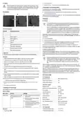
2. Unclip and remove the display unit from the thermostat unit. See [1].
3. Study the wiring diagram on the back of the thermostat unit. See [2].
4. Wire the thermostat unit to the mains supply. Observe the limitations stated in the “Tech-
nical data”.
Used (rechargeable) batteries can be returned to collection points in your municipality, our
stores or wherever (rechargeable) batteries are sold. You thus fulfil your statutory obligations
and contribute to environmental protection.
5. (If required) Wire the supplied external sensor to the thermostat unit.
6. Wire the load to the thermostat unit. Observe the limitations stated in the “Technical
data”.
Batteries/rechargeable batteries that are disposed of should be protected against short cir-
cuit and their exposed terminals should be covered completely with insulating tape before
disposal. Even empty batteries/rechargeable batteries can contain residual energy that may
cause them to swell, burst, catch fire or explode in the event of a short circuit.
7. Insert the thermostat unit into the flush-mounted/surface-mounted box at the installation
location.
8. Secure the thermostat unit through the mounting holes (O) with the included mounting
screws. See [3].
10 Technical data
9. Attach the display unit to the thermostat unit. Make sure thermostat unit locks in place.
10.Switch on/reconnect the power supply to which you have wired the product.
10.1 Integrations
Mobile app control .......................... Smart Life/Smart Living
à The product starts up and the main display shows.
Google Home support .................... Yes
Amazon Alexa support ................... Yes
10.2 Power supply
à The product is ready for use.
Protection class ............................. Class II
7 Selecting the sensor type
After installing the product, set the required sensor type to ensure correct functioning.
Required wire cross-sectional area 2.5 mm2
Input voltage .................................. 90 – 240 V/AC
Input AC frequency ........................ 50/60 Hz
Output voltage ............................... 90 – 240 V/AC
Output frequency ........................... 50/60 Hz
Relay type....................................... Switch relay (1x pole)
Contact capacity............................. max. 16 A
Sensor settings
Menu entry
Purpose
Settings
■
■
■
Sensor type
Select the sensor to be used
for temperature measure-
ments.
Built-in: Internal sensor controls the
temperature.
External: External sensor controls
the temperature.
Internal and external sensor: In-
ternal sensor controls the temperat-
ure and the external sensor is used
as the limiting sensor.
Max. switching capacity.................. 3600 W (resistive load)
660 W (inductive load)
Backup battery................................ 1x CR1220 battery
■
Default: Built-in
10.3 Thermostat
Temperature setting range ............. +1 to +70 °C
Procedure
Temperature display range............. +1 to +70 °C
1. Tap the button
.
2

| General | Details |
|---|---|
| Name | sygonix 3026090 WiFi Thermostat Installation Guide |
| Make | Sygonix |
| Language | English |
| Filetype | PDF (Download) |
| File size | 0.11 MB |
 (1 votes, average: 5.00 out of 5)
 Loading...

sygonix SY-5470190 Wireless Indoor Thermostat Instruction Manual

Sygonix 2992337 DIN Rail Mounted Heating And Cooling Thermostat User Manual

sygonix 2735095 Wireless Heating Thermostat Instruction Manual

Sygonix SY-6052180 Wi-Fi Thermostat Instruction Manual

sygonix 2522212 Installable Thermostat Instruction Manual

Sygonix 2735095 Wireless Indoor Thermostat Instruction Manual

sygonix 2997033 Wi-Fi Radiator Thermostat Instruction Manual


NEOMITIS PRG7 RF 7 Day Two Channel Programmer with RF Room Thermostat Instruction Manual

Danfoss CET B-RF Wireless Electronic Hot Water Cylinder Thermostat Installation Guide

REHAU 13280001001 Thermostat Installation Guide

GENERAL LIFE FH10 Underfloor Heating Thermostat User Manual

Danfoss UT 72 Thermostat Installation Guide

EPH CONTROLS 20221026 RFRA – RF Room Thermostat Instruction Manual

tuya M3 Series Thermostat User Guide

sinope TH1500ZB Smart Double Pole Thermostat Installation Guide

MI-HEAT WT8 WiFi Smart Thermostat User Manual

White Rodgers 1E65-144 Non Programmable Electronic Digital Thermostat Instruction Manual