STELPRO STE241 Low Voltage 24V Electronic Thermostat User Guide


USER’S GUIDE
STE241
LOW VOLTAGE
ELECTRONIC THERMOSTAT (24V)
For further information or to consult this guide online, please visit
INSSTE2410622

| General | Details |
|---|---|
| Name | STELPRO STE241 Low Voltage 24V Electronic Thermostat User Guide |
| Make | StelPro |
| Language | English |
| Filetype | PDF (Download) |
| File size | 0.27 MB |


STELPRO STF362NP Floor Heating Thermostat Owner’s Manual

STELPRO ST302P Programmable Electronic Thermostat Owner’s Manual

STELPRO SAT402ZB Smart Thermostat User Guide

STELPRO ST252NPFF Non-Programmable Electronic Thermostat Owner’s Manual

STELPRO ST402PFF Programmable Electronic Thermostat Owner’s Manual

STELPRO ASMC402 Maestro Zigbee Smart Programmable Thermostat User Guide

STELPRO SIBTE12C Electronic Thermostat Owner’s Manual

STELPRO STZW402+ Electronic Thermostat for The Smart Home Owner’s Manual

STELPRO SIBTE13F Electronic Thermostat User Guide

STELPRO STCP MULTIPLE PROGRAMMING ELECTRONIC THERMOSTAT User Guide
STELPRO STE241 Low Voltage 24V Electronic Thermostat User Guide Overview
Summary of Contents
- Page 1: User's guide for the STE241 low voltage electronic thermostat (24V).
- Page 2: Warning Before installing and operating this product, the owner and/or installer must read, understand and follow these instructions and keep them handy for future reference. If these instructions are not followed, the warranty will be considered null and void and the manufacturer deems no further responsibility for this product. The following instructions must be adhered to in order to avoid personal injuries or property damages, serious injuries and potentially fatal electric shocks. All electric connections must be made by a qualified electrician, according to the electric and building codes effective in your region. Do not connect this product to a supply source other than 24 VAC and do not exceed the load limits specified. Protect the heating system with the appropriate circuit breaker or fuse. You must regularly clean dirt accumulations on the thermostat. Do not use fluid to clean thermostat air vent. Do not install thermostat in a wet place. When a part of the product specification must be changed to improve operability or other functions, priority is given to the product specification itself.
- Page 3: The STE241 low voltage electronic thermostat (24 V) is designed to control relays. The allowed resistive maximum load is 12 W at 24 V (0.5 A). Relays connected to the thermostat can control electric baseboards, convectors, fan heaters, and electric furnaces. This thermostat can be connected to Stelpro relays. The triac contact is quiet. This thermostat is not compatible with resistive loads of more than 12 W at 24 VAC (0.5 A). The thermostat must be mounted on a wall facing the heating unit, at around 1.5 m (5 feet) above the floor level. Do not install the thermostat in locations where temperature measurements could be altered. Avoid locations close to windows, external walls, or heat sources. Ensure the thermostat is not placed in areas with poor air flow or frequent air drafts.
- Page 4: Thermostat mounting and connection Ensure that the air vents of the thermostat are clean and clear of any obstruction. Using a screwdriver, loosen the screw retaining the mounting base and front part of the thermostat. Remove the front part of the thermostat from the mounting base by tilting it upward. The following photos show a connection box installation as a reference only. A connection box is not necessary or required. Align and secure the mounting base using the two screws supplied.
- Page 5: Connect the wires coming from the 24 VAC power source following the appropriate diagram. Connection example #1 shows one baseboard with transformer. Connection example #2 illustrates two baseboards, one connected to a Stelpro RE-153T electronic thermostat with a 24 VAC transformer, and the second connected to a Stelpro RE-153 electronic thermostat without a 24 VAC transformer. The diagrams include details for electric relay with transformer and electric relay without transformer.
- Page 6: Connection example #3 illustrates the use of a standard 24 VAC power source with a transformer. The transformer operates at 24 VAC and connects to a contactor or relay. The color of the wires may vary based on the electronic relays used. The connection diagrams provided are examples only. To reinstall, place the front part of the thermostat back on the mounting base and secure it with the screw at the bottom. After installation, turn on the power. Finally, set the thermostat to the desired setting as detailed in the following section.
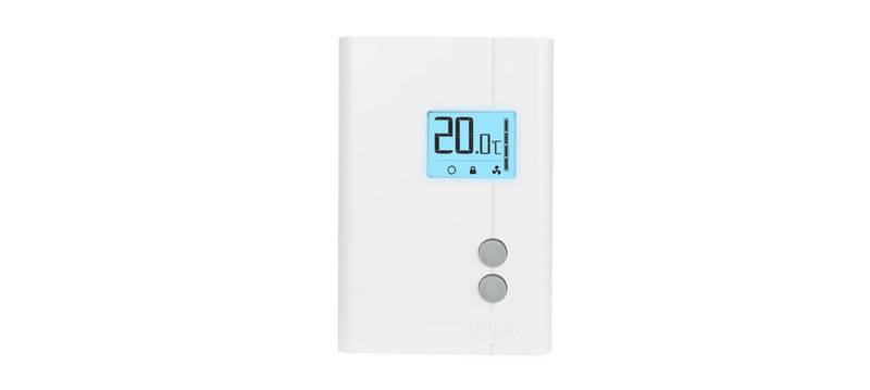
- Page 7: Operation Ambient temperature Timer Heating power used indicator Single programming mode Frost-free warning Day mode Initial start up The thermostat is initially set to Day mode with a default temperature of 21 degrees Celsius. Temperature set points can be adjusted by increments of 0.5°C (1°F).
- Page 8: Day mode and Night mode The thermostat includes a Day mode and a Night mode, both having their own independently adjustable and recorded set point. The standard factory set point adjustment is 21°C (70°F) for the Day mode, and 18°C (64°F) for the Night mode. The current Day/Night mode selection is indicated on the display by the Sun or Moon icon. To manually switch from one mode to the other, simultaneously press down the two buttons and release them immediately. The Night mode features a timer that automatically returns to the Day mode after a selectable time period. The standard factory adjustment of the timer is 8 hours. The thermostat will automatically return to Day mode at the end of the night, and the Day mode temperature set point will become effective at this time. Night mode timer adjustment procedure includes adjusting the Day/Night mode set points at the desired temperatures. From the Night mode, simultaneously press down the two buttons for more than 3 seconds until the Moon icon blinks. The adjustment range for the timer is from 1 hour to 999 hours.
- Page 9: When the adjustment is completed, release the buttons and wait for 5 seconds to exit the adjustment function. The Night mode timer will be automatically reinitialized to the latest recorded value when switching from the Day mode to the Night mode. It is not necessary to readjust the timer every time you switch to the Night mode. The Single programming mode allows alternating between the Day/Night modes and the two corresponding set points over a 24-hour period. Once activated, this mode allows an automatic return to the Night mode after 24 hours. The Single programming mode allows you to define two periods in a single day with different set points. At the end of the 24-hour cycle, the thermostat will return to the Night mode, and the cycle will start over. The 24-hour cycle starts with the Night mode as soon as the Single programming mode is activated. The normal course of a cycle in the Single programming mode includes Night mode activated for the duration of the Night mode timer cycle and Day mode activated for the remaining time of the 24-hour cycle. Adjust the Day/Night set point at the desired temperatures if necessary.
- Page 10: From the Night mode, simultaneously press down the two buttons for more than 3 seconds. Adjust the timer by pressing down the top button to increase the value, or the bottom button to decrease it. The Night mode timer adjustment range is from 1 hour to 23 hours in the Single programming mode. Activate the Single programming mode by simultaneously pressing down the two buttons for at least 3 seconds. When the adjustment is completed, release the buttons and wait for 5 seconds to exit the adjustment function. It is always possible to manually change the Day/Night mode during a 24-hour cycle. At the end of the 24-hour cycle, the thermostat will return to the Night mode and start a new cycle. When turning back on after being powered off, the Single programming mode is deactivated. The thermostat can display the ambient temperature and the set point in degrees Celsius or Fahrenheit. Press down the top button to switch from degrees Celsius to degrees Fahrenheit, and conversely.
- Page 11: When the adjustment is completed, release the buttons and wait for 5 seconds to exit the adjustment function. The level of power used to maintain the temperature at the set point is expressed as a percentage indicated by the number of bars in the thermometer displayed. The heating power used is displayed as follows: 4 bars = 75% to 100%, 3 bars = 50% to 75%, 2 bars = 25% to 50%, 1 bar = 1% to 25%, 0 bar = no heat. The Snowflake icon is displayed when the temperature set point is between 3°C (37°F) and 5°C (41°F). It is possible to impose a maximum temperature set point by activating the security mode. To activate the Security option, from the Day mode adjust the day set point to the desired maximum temperature. Simultaneously press down the two buttons for more than 13 seconds, until the icon appears. To deactivate the Security mode, start by cutting off the thermostat power at circuit breaker and wait at least 20 seconds.
- Page 12: Turn the thermostat power back on and the icon will blink for a maximum of 5 minutes. Simultaneously press down both buttons for 13 seconds to deactivate the Security mode. The Long/Short cycle activation is similar to the Celsius/Fahrenheit degrees adjustment. To switch from long cycle heating to short cycle heating, press down both buttons during 8 seconds in Day mode. The screen displays CC to indicate short cycle or CL to indicate long cycle. In Long cycle, you can adjust the minimum ON/OFF time between the start and shut down of the heating. Adjust the minimum time from 90 to 405 seconds, by increments of 45 seconds. The Long cycle is automatically activated when entering the minimum ON/OFF time selection mode. The thermostat saves parameters in a non-volatile memory to recover them after being shut off. These parameters include Day/Night settings, Single programming mode, and the state of the Security mode.
- Page 13: The parameters are saved every minute if any changes are made, except for the Day/Night mode and the remaining time left on the time-switch. The Single programming mode is not automatically reactivated when the thermostat is turned on. The icon blinks to warn the user that the mode was previously activated when the thermostat was shut off but is no longer active. When power is shut off, the existing Day/Night mode is recovered only if the Single programming mode was previously deactivated. The Day mode is automatically reactivated if the Single programming mode was previously activated. The Security mode is reactivated if it was previously activated. The icon will blink for 5 minutes, during which it is possible to deactivate the Security mode by pressing down both buttons simultaneously for 13 seconds. If the Security mode is not deactivated, it will remain activated and the icon will stop blinking. You can activate the Night light option to permanently turn on the backlight. To activate or deactivate the Night light mode, the thermostat must first be set in Day mode.
- Page 14: Troubleshooting Check if the thermostat is properly connected. Refer to the installation section. Heating is always on. Heating does not run even if the thermostat indicates it is on. Check the power supply at the electrical panel. Check if the heating unit has a switch. If so, ensure that this switch is turned on. The display does not come on. Check the presence of an air stream or a heat source near the thermostat. The displayed ambient temperature is incorrect. Faulty thermal sensor. Contact customer service. Weak luminosity of the display. Check thermostat wirings.
- Page 15: Technical specifications Supply voltage: 24 VAC, 50/60 Hz Inputs / outputs: A 3-positions connector is located at the back of the thermostat. Maximum electrical current with a resistive load: 0.5 A Temperature display range: 3 °C to 40 °C (37 °F to 99.5 °F) Temperature display resolution: 0.5 °C (0.5 °F) Temperature set point range: 3 °C to 30 °C (37 °F to 86 °F) Temperature set point increments: 0.5 °C (1 °F) Storage temperature: -40 °C to 50 °C (-104 °F to 122 °F)
- Page 16: Limited warranty This unit has a 3-year warranty. If at any time during this period the unit becomes defective, it must be returned to its place of purchase with the invoice copy, or simply contact our customer service department. In order for the warranty to be valid, the unit must have been installed and used according to instructions. If the installer or the user modifies the unit, he will be held responsible for any damage resulting from this modification. The warranty is limited to the factory repair or the replacement of the unit, and does not cover the cost of disconnection, transport, and installation.

ENSTO ECO16TOUCH Combination Thermostat Instruction Manual

UNILUX TA640FCW-ULX HVAC Thermostat User Manual

BHT-001Series Round Thermostat User Guide

Rayotec Coloursense Wi-Fi Thermostat Instruction Manual

Danfoss RET230P Electronic Thermostat Instruction Manual

IMIT TA5 Mechanical Thermostat User Manual

Thermafloor HT1 Thermostat White App Electric Mat Thermostat User Guide

ENGO CONTROLS EASY230W Non-Programmable Wired Thermostat User Guide

EVERBILT Electric Upper Thermostat Instructions

GENERAL LIFE FH100S Underfloor Heating Thermostat User Manual