PECO T8168 Performance Pro Thermostat Installation Guide


T8168 CONFIGURATION SERVICE MENUS
CONFIGURE SERVICE MENUS
SERVICE MENU ACCESS
The following Service Menus (SM) commonly require configura-
tion. Please verify that these are set for your specific application.
Additional configuration may be required.
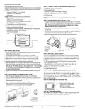
1. Hold lower right and lower left keys for
five seconds.
2. Press Next or Go Back button to select
a Service Menu.
3. Press ▲/ ▼ to select option.
4. Press Done when complete.
SERVICE MENU
NUMBER
•
•
•
•
•
•
•
•
SM 100 = Programmable or Nonprogrammable
SM 110 = System Type
SM 112 = Fan Type
SM 135 = W1 Heat Output NO or NC
SM 170 = Remote Sensors
SM 240 = Number of Programmable Events per Day
SM 395 = Override Duration for Programmable Operation
SM 340 = Keypad Lock Out
SELECTED
OPTION
Menu
100
Feature
Options
Description
Schedule Format
0 = Nonprogrammable (Default)
1 = Programmable
Selects the schedule format. In non-programmable mode all scheduling functions are
removed from the display.
2 = 5-1-1 Schedule Mode
3 = 5-2 Schedule Mode
0 = Disabled (Default)
1 = Enabled (2007 US Format)
101
110
Daylight Savings
System Type
When enabled daylight savings time follows the US 2007 format. (Begins second Sunday of
March at 2AM and ends on the first Sunday of November at 2AM.
1 Stage Heat /1 Stage Cool
Fan: Single Speed
System Type Notes
1
• Fan can be changed from ON/OFF to 0-10 VDC Operation.
• Stage 1 operation includes Y1/ W1 and 0-10 VDC outputs YD./ WD
• System types may disable some service menu unavailablity
• TWF = Three Wire Floating (valve)
2 Stage Heat /1 Stage Cool
Fan: Single Speed
2
1 Stage Heat /1 Stage Cool
Fan: 3-Speed
3
Typical System Configuations:
2 Stage Heat /1 Stage Cool
Fan: 3-Speed
4
2-Pipe Fan Coil with Electric Heat
• Connect the Valve to Stage 1 Cool and the Heat Relay to Stage 1 Heat
• SM110=01,02,03,04,05 or 14
2 Stage Heat / 2 Stage Cool
Fan: 2-Speed
5
• SM171=02 (4-Pipe Operation)
• When using a pipe sensor, Operation of Cool Stage 1 will change. In winter, heating will be
provided from the valve (Stage 1 Cool) and Electric Heat (W1) will be disabled.
Heat Only
6
Fan: Single Speed
Error Detection/ Notification
• Condensate overflow, door open or economizer can be set in Service Menu 175
Cool Only
7
Fan: Single Speed
• Connect external dry switch at S1 and SC. See wiring diagram.
Heat Only
8
Fan: 2-Speed
0-10 VDC Fan Operation
• Change SM112= 01 or 02
Cool Only
9
Fan: 2-Speed
Heat Only
10
Fan: 3-Speed
Cool Only
11
Fan: 3-Speed
Heat: TWF Cool: 2 Stage Cool
Fan: 2-Speed
12
Heat: TWF Cool: 1 Stage Cool
Fan: 3-Speed
13
Heat: 2 Stage Heat Cool: TWF
Fan: 2-Speed
14
Heat: TWF Cool: TWF (Default)
Fan: 2-Speed
15
111
112
Damper Configuration
System Fan Type
0 – Damper Continuous
Damper output is not available when being used as a fan speed.
0: G1 output runs continuously when thermostat is not in System OFF Mode.
1: G1 output cycles with a heat or cool demand.
1 – Damper Cycled with Demand (Default)
0 = On/Off Fan (Default)
0: Uses available fan speeds per Service Menu 110
1: Uses GD output for 0-10 VDC fan. User selection of speed.
HI Speed is set at SM 125-126,LO speed is set at SM 127, MED is set between HI-LO*.
2: Uses GD output for 0-10 VDC fan.
Modulates between Min and Max selections in SM 125-127*.
*Damper Output Available (G1) and runs per SM 111
1 = 0–10VDC FAN Hi-MED-LO Fan
2 = Proportional 0-10VDC Fan
113
114
0-10 VDC Fan Buffer
Valve Stoke Time
0 to 3 Minutes, 30 sec Increments (Default 1) Sets the time delay between fan speeds when SM 112=1
30 Sec To 5 Min (Default 120) Set the amount of time for a TWF valve to go from fully closed to fully Open.
© COPYRIGHT 2025 PECO, INC. ALL RIGHTS RESERVED.
P/N 74599 3220-2406 REV 02
5
| General | Details |
|---|---|
| Name | PECO T8168 Performance Pro Thermostat Installation Guide |
| Make | PECO |
| Language | English |
| Filetype | PDF (Download) |
| File size | 0.47 MB |


PECO T372P Thermostat Instruction Manual

PECO T8168B-2 BACnet Proportional Thermostat Installation Guide

PECO TW180 Thermostat Instruction Manual


SECURE ThermoPlus AS2 Programmable Room Thermostat Instruction Manual

REPTITRIP HMT16N Reptile Heating Mat With Digital Thermostat User Manual

Honeywell Home TH2110DH 1 Cool Programmable Digital Thermostat Installation Guide

Honeywell FocusPRO 5000 Thermostat Installation Guide

EUROTRONIC Sparmatic COMET Programmable Energy-Saving Radiator Thermostat User Manual

HERSCHEL T-MT Mains Powered WiFi Thermostat

BEOK TGR85-EP Underfloor Heating Thermostat User Guide

SALUS CONTROLS IT700 Smart Thermostat Instruction Manual

Honeywell T6811DP08 Digital Thermostat Instruction Manual

Danfoss TP5001B-TP5001RF Programmable Room Thermostat User Guide