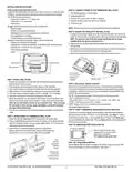
PECO T8168 Performance Pro Thermostat Installation Guide


INSTALLATION INSTRUCTIONS
Select an appropriate thermostat location
Locate the thermostat about four feet (1.2m) above the floor on a wall with good
ventilation, average temperature and good response to temperature changes.
The T8168 may be mounted on a:
PART III: CONNECT POWER TO THE THERMOSTAT WALL PLATE
1. The T8168 operates on 24VAC power.
2. TURN POWER OFF.
3. Connect VAC power to the “24 VAC-1” terminal.
4. Connect the other side to the “24 VAC-2” terminal.
5. Turn Power ON.
• Horizontal or vertical 2” X 4” device box
• Horizontal 4” X 4” device box
• Flat surface
Do not locate the thermostat where it can be affected by:
• Direct sunlight
NOTE: Wait at least one hour for the displayed temperature to stabalize.
• Drafts or dead areas behind doors
• Radiating heat or cool from appliances or equipment
• Concealed pipes or chimneys
PART IV: MOUNT THE T8168 ONTO THE WALL PLATE
!
1. Position the thermostat slightly above the mounted wall plate, then secure the
hooks on the back side of the thermostat to the hinge pockets on the wall plate.
Note: The top back side of the thermostat should slip into the hinge
pockets easily. Do not use excessive force.
2. Align the pins on the back side of the thermostat with the terminal blocks on
the wall plate.
3. Gently bring down the thermostat onto the wall plate so the pins on the back of
the thermostat fit into the terminal blocks on the wall plate.
4. Attach the retaining screw to the underside of the thermostat as shown.
• Outside walls or unheated/uncooled areas
Required components (not included, unless otherwise specified):
• Screws and wall anchors (included)
• Screwdrivers: Phillips (for wallplate); small flathead (for terminal blocks)
• Drill with 3/16” drill bit (or 7/32” for plaster)
• Wire cutter and stripper
• Level
Mounting holes
Wiring passage
Mounting holes
Secure hooks
on back side of
thermostat to
Retaining screw
wallplate.
PART I: INSTALL WALL PLATE
1. Position the wall plate on the wall with the directional arrow pointing up and
terminal blocks facing outward.
PART V: SET CLOCK, MONTH, AND DAY
2. Pull equipment wires through the center opening of the wall plate.
3. Use a level to determine the best horizontal wall plate mounting position.
4. Mark positions of screw holes (two) with a pencil and remove wall plate.
5. Drill holes at pencil-marked locations (3/16” for drywall, 7/32” for plaster).
6. Insert the wall anchors in the holes, tapping them into place.
7. Mount the wall plate onto the wall and insert screws through mounting holes.
Assure that all loose wires come through the center opening of the wall plate.
Note: Do not over-tighten screws or use excessive force. This can cause
the wall plate to warp and may cause intermittent connections between
the base and the thermostat.
When power is first applied to the thermostat, it will activate the clock display.
It is recommended that time and day are entered before performing advanced
configuration. Setting the clock can also be accessed by selecting MORE then
CLOCK. Set clock as follows:
• ▲/ ▼= Arrows set selection. Note: The flashing option is the default selection.
• NEXT = Advances to next menu.
• Menu selections are: 12 to 24 hour format - Hour - Minutes - Year - Month - Day
• DONE = Press Done when operation is complete.
NOTE: Display of Clock is not available when configured for
non-programmable operation.
PART VI: VERIFY THERMOSTAT OPERATION WITH SYSTEM TESTS
8. Cap off any unused wires and terminate properly according to local building
codes.
System test verification is highly recommended to verify thermostat operation.
See Service Menus: 600, 610, 620. For all system tests, press Next to continue
to the following system test, or next available Service Menu. Press Done only if
finished performing all system tests. Pressing Done exits the Service Menus and
turns off all active outputs.
PART II: ATTACH WIRES TO THERMOSTAT WALL PLATE
1. Select the terminal designations that correspond to the system type.
2. Using a small flathead screwdriver, loosen the screws on the terminal blocks,
Strip the insulation of each wire at a proper length (about 1/4” or 64 cm) and
insert wires into the terminal blocks.
PART VII: REMOVE BATTERY INSULATOR TAB
3. Assure that no uninsulated wires are exposed: Cap off and
place a wire-nut on any unused wires. Assure that the attached
wires fit into the cavity on the back side of the thermostat.
Remove Insulator Tab after power
is applied.This tab protects onboard
battery prior to installation.
This battery backups up the clock.
Insert
wires into
appropriate
terminal
PART VIII: T8168 CONFIGURATION
Service Menus (SM) are used to configure the T8168. Access to specific SM’s
may be limited based on other configuration. See Page 5.
blocks.
Enlarged area
shows wire
insertion point at
terminal block.
© COPYRIGHT 2025 PECO, INC. ALL RIGHTS RESERVED.
P/N 74599 3220-2406 REV 02
2
| General | Details |
|---|---|
| Name | PECO T8168 Performance Pro Thermostat Installation Guide |
| Make | PECO |
| Language | English |
| Filetype | PDF (Download) |
| File size | 0.47 MB |


PECO T372P Thermostat Instruction Manual

PECO T8168B-2 BACnet Proportional Thermostat Installation Guide

PECO TW180 Thermostat Instruction Manual

DAIKIN IM 1366 Remote Integrated Thermostat Instruction Manual

Drayton RF902 Digistat 3rd Generation Wireless 2-Channel Programmable Thermostat Installation Guide

Danfoss ECtemp 531 Electronic Thermostat Installation Guide

tuya MTS700N Wireless Thermostat User Manual

SALUS BTR230 Room Thermostat User Guide

LAE AC1-2W Digital Thermostat Instruction Manual

Rheem RETST700SYS EcoNet Smart Thermostat Owner’s Manual

ENGO EASYBATB Wired Battery Thermostat User Guide

technoswitch TE315 Recessed Touch Thermostat User Guide

Beca BAC-7000 Smart Knob Thermostat User Guide