
Milesight WT101 Smart Radiator Thermostat User Guide












Smart Radiator Thermostat
Featuring LoRaWAN®
WT101
User Guide


| General | Details |
|---|---|
| Name | Milesight WT101 Smart Radiator Thermostat User Guide |
| Make | Milesight |
| Language | English |
| Filetype | PDF (Download) |
| File size | 0.4 MB |
 (1 votes, average: 5.00 out of 5)
 Loading...

Milesight WT201-868M Smart Thermostat User Guide

Milesight WT201 Airteq Smart Thermostat User Guide

Milesight WT201 Smart Thermostat User Guide

Milesight WT30x Smart Fan Coil Thermostat User Guide

Milesight WT101 Smart Radiator Thermostat User Guide Overview
Summary of Contents
- Page 1: Smart radiator thermostat featuring LoRaWAN. User guide.
- Page 2: Safety precautions are essential to follow to avoid loss or damage. The device must not be disassembled or remodeled in any way. It is not intended to be used as a reference sensor, and inaccurate readings may lead to damage. Do not paint or clean the PIR lens, as it will affect detection. Avoid placing the device outside the specified temperature range. Keep the device away from naked flames, heat sources, sunlight, cold sources, liquids, and extreme temperature changes. Remove the battery if the device will not be used for an extended period to prevent leakage. The device should never be subjected to shocks or impacts. The WT101 conforms to CE and RoHS requirements. All information in this guide is protected by copyright law.
- Page 3: Revision history provides a record of changes made to the document. The initial version was released on September 15, 2023. The document version is 1.0.
- Page 4: Product introduction Overview Key features Hardware introduction Packing list Hardware overview Button and LED patterns Dimensions (mm) Power supply Installation instruction Adapter selection Thermostat installation Operation guide NFC configuration LoRaWAN® settings General settings Advanced settings Calibration settings Heat schedule Maintenance Backup Upgrade Reset to factory default Device payload Basic information Sensor data Downlink commands
- Page 5: Product introduction provides an overview of the WT101, a LoRaWAN radiator thermostat designed for managing heating-control systems. The device allows for one pre-set date period and up to 16 customized heating plans, facilitating smart management of heating systems and cost savings. WT101 is sensitive to environmental changes, quickly responding to abnormal temperature differences and extreme low temperatures by adjusting the valve opening. It is compliant with Milesight LoRaWAN gateway and IoT Cloud solution, enabling remote control of room temperature and other sensors or appliances via a webpage or mobile app. Key features include automatic and manual temperature adjustment with time-controlled regulation and up to 16 heating schedules. The built-in temperature sensor allows for environmental detection and accurate control. It features an intuitive LED display for easy adjustment in various installation environments. The device supports open-window detection and freeze protection, enhancing safety and efficiency. It includes a child-lock feature for tamper-proof security in public areas. The WT101 is easy to install with a simple lock design and is compatible with standard LoRaWAN gateways and network servers.
- Page 6: Theft-deterring collar kit. Quick start guide. Warranty card. Valve adapter (optional). If any of the above items are missing or damaged, please contact your sales representative. The motor is used to push the radiator valves to open or close as required.
- Page 7: Button and LED patterns indicate the device's status. Light on means the device is on, while light off indicates it is off. To check the on/off status, quick press the reset button or rotate the control knob. Reboot the device by pressing and holding the reset button for more than 3 seconds. To reset to factory default, press and hold the reset button for more than 10 seconds. Motor stroke calibration is indicated by specific LED patterns. Tamper status is shown when the device is installed and the tamper calibration button is pressed. The device removal is indicated when the tamper calibration button is released. To access the power supply, separate the base plate from the device by rotating it anticlockwise. Open the metal battery cover by pushing it.
- Page 8: Install the two batteries with correct direction, which is shown on the battery cover. Restore the battery cover in place. After installing the batteries, the device will turn on automatically and the LED display will light on for 3 seconds. The device can be powered by 1.5V AA Li-FeS2 or alkaline batteries, not Li-SoCl2 batteries. It is suggested to use Li-FeS2 batteries which have longer battery life than alkaline batteries. Make sure both batteries are newest when installed, or battery life will be reduced. After installing the batteries, the device will show and report battery level as 100% at the first time even for old batteries. The device will calculate the battery level after one hour. The valve base plate can be used for all valves with a thread size of M30 × 1.5 mm from the most common manufacturers without any accessories. For other valve types, select the corresponding adapter and mount it on the valve.
- Page 9: Thermostat installation involves several key steps. Place the base plate on the valve or valve adapter and screw it tightly, ensuring the groove on the base plate faces the display direction. Rotate the device clockwise to secure it on the base plate and fix the hex socket cap fixing screw. The calibration and tamper button will be pressed during this rotation, starting the calibration process. The LED will blink twice to indicate that calibration is completed. Cover the fixing screw with the screw cap. Fix the theft-deterring collar to the base plate using a screw and nut.
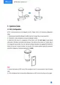
- Page 10: Operation guide NFC configuration WT101 can be monitored and configured via NFC. Download and install the Milesight ToolBox App from Google Play or Apple App Store. Enable NFC on the smartphone and launch Milesight ToolBox. Attach the NFC area of a smartphone to the device and click NFC Read to read device information. The basic information and settings of the device will be shown on ToolBox App if it’s recognized successfully. You can read and configure the device by tapping the Read/Write device on the App. To protect the security of the device, please change the password when first configuring. Ensure the location of the NFC area of the smartphone and it’s recommended to take off the phone case. If the smartphone fails to read/write configurations via NFC, remove the phone and try again.
- Page 11: LoRaWAN settings allow configuration of AppEUI, Join Type, Application Key, and other basic information. Device EUI is a unique ID of the device found on the label. The default App EUI is 24E124C0002A0001. The default port for sending and receiving data is 85. OTAA and ABP modes are available for connection. Application Key for OTAA mode has a default value. Nwkskey for ABP mode has a default value. DevAddr for ABP mode is derived from the serial number. LoRaWAN versions V1.0.2 and V1.0.3 are available. The work mode is fixed as Class A.
- Page 12: Frequency If the device does not receive an ACK packet from the network server, it will resend data once. Confirmed Mode The device will send a specific number of LinkCheckReq MAC packets to the network server every reporting interval or every double reporting interval to validate connectivity. Rejoin Mode The device will send a specific number of LinkCheckReq MAC packets to the network server every reporting interval to validate connectivity. When the rejoin mode is enabled, set the number of LinkCheckReq packets to send. Allow network server to adjust data rate of the device. If ADR is disabled, the device will send data via this spread factor. Transmit power of the device. Select OTAA mode if you use Milesight IoT cloud to manage devices. Only OTAA mode supports rejoin mode. Please contact sales for device EUI list if there are many units.
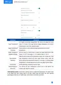
- Page 13: Parameters Description The interval of reporting battery level, temperature, motor status to network server. Default: 10 min, Range: 1 - 1440 min Set the unit of temperature displayed on the LED display and configuration page. Set the LED display direction to suit thermostat mounting orientation. Disable or enable the device to control the valve to adjust temperature. Select from automatic temperature control or valve opening control. When the device detects the temperature is lower than the threshold temperature, control the valve opening status every 10 minutes. Lock the control knob to control the valve. Change the password for ToolBox App to write this device. Automatic temperature control: set target temperature to control the valve opening status.
- Page 14: Set target environment temperature. The device will adjust the valve every 10 minutes if the gap between target temperature and current temperature is more than tolerance value. Set the tolerance value between target temperature and current temperature. Set the range for control knob to adjust the target temperature. Max range: 16 - 35 °C, min range: 5 - 15 °C, default range: 10 - 28 °C. When the device detects the temperature drops over cooling rate, it will stop temperature control and report open window status. When the device detects the temperature rising for 10 minutes or reaching target temperature, it will start temperature control and report normal status. Set the detecting condition of window open. The device will start temperature control even if it still detects the window open after this interval. Control valve opening status to adjust the temperature. 0% means valve is all closed and 100% means valve is all open. The valve opening percentage can be set via ToolBox App, control knob or downlink command.
- Page 15: When rotating the control knob, the LED display will show corresponding valve opening percentage and current temperature. Every rotating step is 5%. When setting the valve opening percentage as 100%, the LED display will only show 99. Motor stroke calibration: click to calibrate the motor stroke when the device is installed to the valve. Temperature calibration: set the calibration value, the device will add calibration value to the current temperature value and report the final value. WT101 supports to set at most 16 heat schedules within 1 pre-set date period. Sync the device time via ToolBox App. The device can also ask for the time from network server when setting LoRaWAN version as 1.0.3.
- Page 16: Set a heating date period and the reporting interval except the heating date period. Temperature control will stop during the non-heating period. Set time-based control events that only execute within the heating date period. If the repeat day is not selected, this event will only execute once.
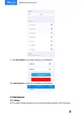
- Page 17: Click Save Schedule to export above settings as a schedule file. Click Select Schedule to import the schedule file to another device. WT101 supports backup templates for easy and quick configuring devices in bulk.
- Page 18: Go to the template page on the app and save the current settings as a template. The saved templates are also editable. Select one saved template and click write, then attach the smartphone to another device via NFC to reuse the template. Slide the template item to the left to edit or delete the template. Click the template to edit the configurations.
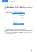
- Page 19: Upgrade firmware from the Milesight website to your smartphone. Use the ToolBox App to import firmware and upgrade the device. Operation on ToolBox is not supported during the upgrade. Only the Android version of ToolBox supports the upgrade feature. WT101 supports two methods to reset the device. Reset via hardware by pressing and holding the reset button for more than 10 seconds. Reset via ToolBox App by tapping Reset and using NFC to complete the process.
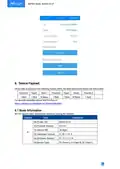
- Page 20: Device payload data is based on a specific format in HEX, following little-endian order. The data structure includes channels, types, and corresponding data bytes. Basic information is reported by WT101 when joining the network. Channel 0b indicates that the device is powered on. Protocol version is represented as 01. Device serial number consists of 16 digits. Hardware version is denoted by ff. Software version is indicated by 0a. Device type is represented by 0f, with specific class designations. For decoder examples, files are available on GitHub.
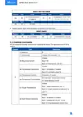
- Page 21: Channel Type Value Power On Reserved Protocol Version Hardware Version Software Version Device Type Sensor Data Battery Level Current Temperature Target Temperature Valve Opening Percentage Tamper Status Open Window Detection Motor Calibration Result Motor Stroke Freeze Protection Motor Position
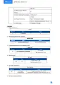
- Page 22: Automatic temperature control periodic packet reports as reporting interval (10 minutes by default). Motor stroke value indicates the position of the motor. Valve opening control periodic packet reports as reporting interval (10 minutes by default). Motor calibration packet reports when the motor starts calibrating. Open window detection reports when detecting the window open or returns back to normal status. Freeze protection reports when freeze protection is triggered or released. Temperature values are calculated based on channel data. Motor position values indicate the current state of the motor. Channel types and values are essential for understanding the system's status. Periodic reporting intervals are set to 10 minutes by default.
- Page 23: Value Channel Channel Type Freeze protection is triggered. Temperature: 15 00 =>00 Tamper packet: report when the device is removed from base plate. WT101 supports downlink commands to configure the device. The application port is 85 by default. Reboot command. Temperature control modes include automatic and valve opening control. Target temperature settings include enable/disable options. Open window detection feature.
- Page 24: Unit: min Release open window status Valve opening percentage Freeze protection Child lock Reboot the device. Set reporting interval as 2 minutes. Enable temperature and set calibration value. Set time zone. Set target temperature. Set open window detection.
- Page 25: Channel Type Value 01=enable (Open Window Detection) Cooling rate: 1e=30*0.1=3 °C/min Stop control time: 3c00=>00 3c=60 minutes Set valve opening percentage. Type b4 (Valve Opening Percentage) Value 32=>50% Set freeze protection. Type b0 (Freeze Protection)

OJ ELECTRONICS UTN5 Non Programmable Touch Thermostat Instruction Manual

lae AC2-2 Two Stage Thermostat Instructions

BEOK TGR86 Smart Underfloor Heating Thermostat User Guide

Schneider Electric TC900 Series Space Logic Thermostat Instruction Manual

AeoTec Radiator Thermostat ZWA021 User Manual

AVATTO WT598 1T1 Smart Thermostat

GROHE 26984001 Vitalio Comfort 250 Shower System with Bath Thermostat Installation Guide

Honeywell CT87A Round Thermostat Instruction Manual

Meross MTS200HK Smart Thermostat User Manual

King K901-B Wifi Programmable Thermostat Instruction Manual