LUX PSPH521 Series Programmable Heat Pump Thermostat Instruction Manual


C
A
U
T
I
O
N
N O T E
When replacing batteries, you have
approximately 1 minute before programs are lost.
Do not allow wires to touch each other or parts on thermostat. Wires must be
trapped between black spacer and brass terminal. Also, be sure to tighten securely
all terminal screws.
1. Remove fresh batteries from their carton.
REPLACE BATTERIES WHEN
INDICATOR APPEARS
TERMINAL DESIGNATIONS
2. Remove body of thermostat as described at bottom of
first column.
NEW THERMOSTAT
TERMINAL
DESIGNATIONS
OLD TERMINAL
DESIGNATIONS
TYPICAL
CONNECTION
3. Remove the battery clip and batteries.
4. Install two Energizer® or DURACELL® "AA" size
alkaline batteries in the battery clip. Observe the
polarity marking shown in the clip.
C
A
U
T
I
O
N
The Unit is protected against normal
static electric discharges. However, in
extremely dry weather you should touch
another metal object before the Unit to
avoid potential loss of programs.
B
C, X, X1, X2, Z
E, K
B
Heating Changeover Valve
Common
WARNING: Use Energizer® or DURACELL®
Alkaline Batteries Only.
C
5. Place body back on the wall. Hook the bottom of the body onto the base, swing the body up, and
snap the body onto the base.
E
Emergency Heat Relay
Fan Relay
Installation is now complete. Be sure to turn the power back on to your heating and /or air conditioning
system. If this is the first time you are installing batteries, the thermostat will display “SUN 12:00 AM”.
Within 90 seconds the thermostat will begin to display the room temperature alternately with the time.
To correct the display, see “Setting the TIME and DAY,” after you set the programs.
G, F
G
L, A, A1
0
TAPE OFF
Check Heat Pump Indicator
Cooling Changeover Valve
This thermostat is “armchair programmable”
You can make any program or setting
0
R
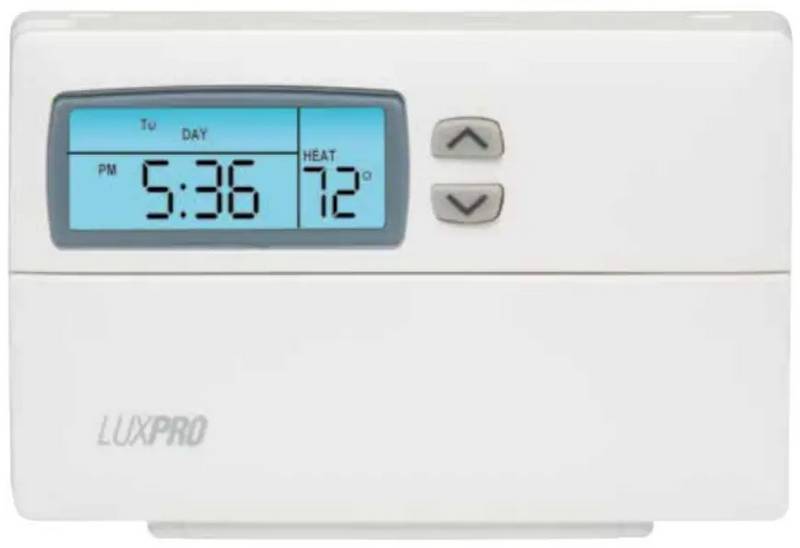
OPERATION
The Unit alternately displays the current time
changes with the thermostat body off or on
24V System or Heating
Transformer
and the room temperature. It also
the wall thermostat base.
R, V
displays the day of the week and the
currently active program period that is controlling the temperature: MORN, DAY, EVE, or NIGHT.
Stage 2 Heating Relay or
Auxiliary Heat Relay
W2, H2, R4, W3, Y
Y, C1, M, Y1
W2
Y
The set point temperature will appear in the right side of the display. In the winter, set the system switch
to HEAT to control your heating system. In the summer, set the switch to COOL to control your air
conditioner. In spring and fall or when windows are open, you can set the system switch OFF.
Stage 1 Compressor
Contractor
Setting the FAN switch to AUTO automatically runs your system’s fan during heating and cooling.
Setting the FAN switch to ON runs your system’s fan continuously even without heating or cooling.
NOTE: A typical hookup will require either a "B" or "O" wire, but not both.
If you have both a "B" and "O" wire, please call technical service.
TYPICAL HOOKUP
THE BUILT IN PROGRAMS
PERIOD
HEAT
COOL
Push in the RESET key. This sets the
built-in heating and cooling programs.
To review the built-in programs,press
NEXT or PREVIOUS repeatedly; when
you are done, press RETURN.
E
G
Y
R
O
W2
B
C
WEEKDAYS
MORN
DAY
6:00 AM 70° 6:00 AM 78°
8:00 AM 62° 8:00 AM 85°
6:00 PM 70° 6:00 PM 78°
preprograms
EVE
HEAT
CHANGEOVER
VALVE
COOL
CHANGEOVER
VALVE
EMERGENCY
HEAT RELAY
COMPRESSOR
RELAY
NIGHT 10:00 PM 62° 10:00 PM 82°
You can use the built-in programs as
shown, or change them as you wish.
Each day is divided into four periods.
Each period has its own starting time
and temperature.
MORN
DAY
6:00 AM 70° 6:00 AM 78°
8:00 AM 62° 8:00 AM 85°
6:00 PM 70° 6:00 PM 78°
FAN
RELAY
AUX HEAT
RELAY
COMMON
SAT & SUN
preprograms
EVE
1
NIGHT 10:00 PM 62° 10:00 PM 82°
L1
(HOT)
L2
(COMMON)
P
R
O
G
R
A
M
M
I
N
G
C
H
A
R T
POWER SUPPLY PROVIDE DISCONNECT MEANS AND OVERLOAD
PROTECTION AS REQUIRED.
DAY
PERIOD
HEAT
COOL
1
TEMP.
TIME
TEMP.
TIME
MORN
DAY
MONDAY
THROUGH
FRIDAY
SETTING THE FAN AND SYSTEM SWITCHES
EVE
NIGHT
MORN
DAY
FAN ON
FAN AUTO
EMER
The fan runs continuously for increased air circulation.
SATURDAY
AND
Normal Setting. Fan is energized with the system.
Auxiliary heat is used for heating. The compressor is deenergized.
The thermostat controls your heating.
EVE
SUNDAY
NIGHT
HEAT
OFF
Both heating and cooling are off.
COOL
The thermostat controls your cooling.
RESET
SET
WEEKDAY
PROGRAM
SET
WEEKEND
PROGRAM
FAN
AUTO
ON
EMER
HEAT
OFF
INSTALLING BATTERIES
HOLD
NEXT
COOL
SET
DAYTIME
RUN
The Unit requires batteries to
retain its programming in
memory. Replace the batteries
when the REPLACE indicator
appears in the display or at
least once a year.
SIMPLIFIED INSTRUCTIONS
TO SET PROGRAMS
TO SET TIME & DAY
TEMPORARY TEMPERATURE OVERRIDE
• Rotate Dial to SET WEEKDAY • Rotate Dial to SET
•Press UP/DOWN to adj st set temperat re
© COPYRIGHT 2004 LUX PRODUCTS CORPORATION. ALL RIGHTS RESERVED
2
| General | Details |
|---|---|
| Name | LUX PSPH521 Series Programmable Heat Pump Thermostat Instruction Manual |
| Make | LUX |
| Language | English |
| Filetype | PDF (Download) |
| File size | 0.18 MB |


LUX TX700U Universal Thermostat Instruction Manual

LUX TX500Ub Non Programmable Thermostat Instruction Manual

LUX TX1500E Programmable Thermostat Instruction Manual

LUX CAG1500 SERIES Smart Temp Electronic Thermostat Instruction Manual

LUX PSP511A Smart Temp Electronic Thermostat Instruction Manual

LUX PSP511A Series Programmable 5-2 Thermostat Instruction Manual

LUX DHP2120 Battery Powered Non Programmable Digital Heat Pump Thermostat Installation Guide

CH200SA Versatile Deluxe Low Voltage Thermostat Installation Guide

LUX TH10 Heating Only Mercury FREE Manual Thermostat Instruction Manual
LUX PSP511Ca Programmable Thermostat Instruction Manual


tekmar TEK564 Invita WiFi Thermostat User Manual

nest B08K2M13NY Thermostat E Smart Thermostat Installation Guide

BEOK TDS21WIFI-AC Fan Coil Thermostat Instruction Manual

Honeywell TC500A-N Commercial Thermostat User Guide

SIEMENS RDE100.1 Programmable Room Thermostat Instruction Manual

Wengart TP808-S-2 Low Voltage Thermostat User Guide

Honeywell TH5220D1003 Heater Thermostat Owner’s Manual

Blue Universal OH-1202 Touchscreen Thermostat Instruction Manual

Danfoss UT 72 Thermostat Installation Guide

thermokon JOY SR 5DO Electronic Fancoil Thermostat User Guide