Hunter 44110 Set And Save Programmable Thermostat Owner’s Manual


®
3
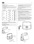
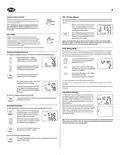
■ Position wallplate on wall and pull existing wires through large opening. Then level for ap-
pearance. Mark holes for plastic anchors provided, if your existing holes do not line up with
those on the Hunter wallplate.
Wire Labeling (Continued)
■ After labeling wires, disconnect them from the existing thermostat terminals.
■ Remove existing wallplate. To make sure wires do not fall back into wall opening, you may
want to tape them to the wall.
■ Drill holes with 3/16” bit and gently tap anchors into the holes until flush with wall.
■ Reposition wallplate to wall, pulling wires through large opening. Insert mounting screws
provided into wall anchor and tighten. See Figure 3.
■ If hole in wall is larger than necessary for wires, seal this hole with insulating material so that
no hot or cold air can enter the back of the thermostat from the wall. This air could cause a
false thermostat reading.
NOTE: 5-wire Systems
If your thermostat has one wire marked R or RH (2, 3, or 4-wire system), then leave the jumper
wire between the RH and RC terminals on the wallplate. Otherwise, if you have separate RH and
RC wires (5-wire system), then remove the jumper wire between the RH and RC terminals.
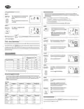
If the code letter on your
existing thermostat is
then mark the wire
with label shown
and connect to thermostat
terminal shown
RH
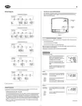
Connect Wires and Mount Thermostat to Wallplate
RH, R, VR or4
24 Volt
x
■ Match and connect the labeled wires to the appropriate coded terminal screws on the
wallplate. (See Figure 4, 5.) Ignore any wires which may be present, but which were not con-
nected to the old thermostat.
RC
RC, VC
x
■ Refer to the Wiring Diagrams below to be sure your system is wired correctly.
24 Volt Cool
■ Be sure to tighten the terminal screws securely, otherwise a loose wire could cause opera-
tional problems with your system or thermostat.
G
G or F
Fan
x
■ Push excess wire back into the hole to prevent interference when installing the thermostat to
the wallplate.
■ Make sure the System Switch is set to OFF, and the Fan Switch is set to AUTO.
Y, C or M
Y
■ Insert the bottom tab on the thermostat body into the slot at the bottom of the wallplate.
Press the top of the thermostat body to snap it into the wallplate. Refer to Figure 6. (NOTE:
Do not force the thermostat onto the wallplate, as the terminal pins may be
damaged. If it does not snap properly, the thermostat may not work.)
x
Air Conditioning
Compressor
W
W or H
x
■ Insert the two AA size alkaline batteries, observing the polarity marked inside the battery
compartment.
Heating
■ Switch on the main power at the panel or furnace.
Table A
NOTE: Do not connect a “Common” wire (sometimes labeled “C”) to any terminal on
this thermostat. Tape up the wire and do not use. This wire provides electricity to non-
battery powered thermostats.
Mount Wallplate and Thermostat
■ Remove the wallplate from your thermostat by pressing the release tab on the bottom of the
thermostat. See Figure 2.
RH
x
G
Rc Rh
Y
W
Figure 2
Figure 4
Figure 5
Rc
G
Figure 3
Figure 6
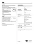
| General | Details |
|---|---|
| Name | Hunter 44110 Set And Save Programmable Thermostat Owner’s Manual |
| Make | Hunter |
| Language | English |
| Filetype | PDF (Download) |
| File size | 0.34 MB |


industrie technik TF Frost Protection Thermostat Instruction Manual

Provirtec TH-01 Smart Thermostat User Manual

Wengart TP808 Low Voltage Thermostat User Guide

PECO T8168B-2 BACnet Proportional Thermostat Installation Guide

ENGO CONTROLS EONE-BATW, EONE-BATB Internet Controlled Thermostat User Guide

HITACHI ATW-RTU-05 Wireless Intelligent Room Thermostat Instruction Manual

GENERAL HT300S Wired Room Thermostat User Guide
COLDBUSTER CB Dual Thermostat User Manual

GLOBAL CEG Series Convector with Thermostat Instruction Manual

alza WT410 Thermostat User Manual