
Hunter 44110 Set And Save Programmable Thermostat Owner’s Manual



®
2
Congratulations!
ENERGY STAR® PARTNER
As an ENERGY STAR® Partner, Hunter Fan Co. has determined that this programmable thermostat
meets the ENERGY STAR® guidelines for energy efficiency.
Your new Hunter thermostat will provide years of reliable service. By saving energy, your
thermostat will pay for itself during its first season of use. Thank you for buying a Hunter
product!
Please read this manual for complete instructions on installing and operating your thermostat. If
you require further assistance, call Hunter Technical Support at 1-888-830-1326 from 8am to 5pm
Central Time.
Before starting, remove the mylar label from the LCD display.
IMPORTANT INFORMATION
INSTALLATION
1. This thermostat is designed to work on the following systems:
What You Need
Gas - Standing Pilot
Gas - Electronic Ignition
Gas - Fired Boilers
Gas - Milivolt Systems
Oil - Fired Boilers
Electric Furnace
Electric Air Conditioning
This thermostat includes two #8 slotted screws and two wall anchors for mounting. To install
your thermostat, you should have the following tools and materials.
■ Slotted Screwdriver(s)
■ Small Philips screwdriver
■ Hammer
This thermostat will NOT control single-stage or
multi-stage heat pumps or 110/220 V baseboard
electric heating systems.
Oil - Fired Furnace
2. Temperature Range
■ Electric drill and 3/16” bit
■ Two 1.5 V (AA) size alkaline batteries
This thermostat can be programmed between 45˚F and 95˚F (7˚C and 35˚C). It will display room
temperatures from 30˚F to 99˚F (0˚C and 37˚C). “HI” will be displayed if the temperature is higher
than 99˚F (37˚C), and “LO” will be displayed if the temperature is lower than 30˚F (0˚C).
This thermostat will automatically cut-off in Heat mode if the temperature rises above 95˚F
(35˚C), and automatically cut-off in Cool mode if the temperature drops below 40˚F (4˚C).
Remove Old Thermostat
CAUTION: Do not remove any wiring from existing thermostat before reading the in-
structions carefully. Wires must be labeled prior to removal.
3. Compressor Protection
This thermostat provides a 3.5 minute delay after shutting off the cooling system before
it can be restarted. This feature will prevent damage to your compressor caused by rapid
cycling. It does not prevent a rapid compressor restart due to short power outages.
■ IMPORTANT! Turn off the power to the furnace at the main power panel or at
the furnace.
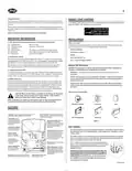
■ Remove existing thermostat cover and thermostat. See Figure 1. Some thermostats will have
screws or other locking devices that must first be removed. Once the wall mounting plate is
exposed, look for wires.
4. Battery Warning
Two fresh AA alkaline batteries should provide well over one year of service. However, when
the batteries become drained, the Low Battery Indicator will flash on the display. When this
message occurs, install new alkaline batteries. You have approximately 1 minute to change
the batteries and keep thermostat’s clock and program settings. Once the batteries have
become too low to ensure proper operation, your system will be turned Off, and the display
will be cleared except for flashing Low Battery Indicator on the LCD display.
If wires are not visible, they may be connected to the back of the wallplate. Again, look for
screws, tabs, etc. Some models have doors that open to expose wires and mounting screws.
See Figure 1.
Typical Home Thermostats
CAUTION: When only the battery icon flashes on the display, the thermostat
is shut down, and your system will no longer operate. In this condition,
there is no temperature control of your dwelling.
NOTE: If you plan to be away from the premises over 30 days, we recommend that
you replace the old batteries with new alkaline batteries prior to leaving.
Wall Mounting Plate
Thermostat
Cover
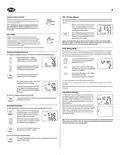
FEATURES
Day / Time Key: Used for entering the Clock
setting mode. Use with the Up and Down keys
to set the time and day.
Front Door: Covers keys when not used for neat
appearance. Open by lifting from the bottom
Wall Mounting Plate
Thermostat
Cover
LCD Display: Shows
Time, Day, Temperature,
Program Number, and
other feature information
as required.
Up and Down Keys: Keys for
changing the Temperature
setting. Also used for increasing
and decreasing selections in the
Time, Program, and Span
functions.
Figure 1
Wire Labeling
Low Battery Indicator:
Flashes when batteries
need to be replaced.
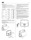
■ Each wire coming from the wall to the existing thermostat is connected to a terminal point on
that thermostat. Each of these terminal points is usually marked with a code letter as shown
in Table A below.
Program Key: Used for entering
and modifying Programs. Use
with the Up and Down keys to
set times and temperatures.
Press when in Clock setting
mode to select between 12 and
24 hour clock modes.
System Switch:
Selector switch for
Heat, Cool, and Off
M
AM
■ The number of wires in your system can be as few as two (for heat only systems), as many as
eight, or any number in between. If you follow the labeling procedures correctly, you do not
have to be concerned about how many wires there are.
4
TEMP
Fan Switch: Fan
switch for Automatic
or Continuous fan
operation.
system
heat
program
off
day/time
reset
cool
Filter Key: Resets filter change
counter to zero.
■ There is often no terminal marking on the existing thermostat of
filter
fan
two wire, heat only systems. Just connect either of the wires to the
RH terminal, then connect the other wire to the W terminal to
complete the circuit.
G
Y
auto
on
hold
W
RH
RC
Battery Compartment:
Front access allows
easy insertion of two
AA 1.5V batteries.
Hold / Return Key: Used for
/return
setting a permanent (vacation)
hold, and for returning to the
normal display from Day & Time
setting, Programming, or Span
setting modes.
■ IMPORTANT! BEFORE DISCONNECTING ANY WIRES, APPLY THE
SELF-ADHESIVE LABELS PROVIDED TO THE WIRE AS SHOWN IN
TABLE A BELOW. (For example, attach the label marked W to the
wire that goes to the W or H terminal on your existing thermo-
stat.) IGNORE THE COLOR OF THE WIRES since these do not al-
ways comply with the standard.
Reset: Press with a paper clip to reset the
thermostat and return to power-up settings.
Battery Release Lever: Push
to pop batteries loose.
(Continued)

| General | Details |
|---|---|
| Name | Hunter 44110 Set And Save Programmable Thermostat Owner’s Manual |
| Make | Hunter |
| Language | English |
| Filetype | PDF (Download) |
| File size | 0.34 MB |
 (1 votes, average: 5.00 out of 5)
 Loading...


BAXI uSense 2 Wired Smart Thermostat Gateway Installation Guide

namron 1402746 Touch Thermostat Instruction Manual

STELPRO ST252NPFF Non-Programmable Electronic Thermostat for Fan Heaters Owner’s Manual

sygonix 2735095 Wireless Heating Thermostat Instruction Manual

Braebur 1230 Non Programmable Thermostat Instruction Manual

SALUS RT310i Internet Thermostat Installation Guide

Danfoss TP5001B Programmable Room Thermostat User Guide

BEOK TDS75 Touch Screen Thermostat User Manual

Global Sources WT598 1T1 Smart Thermostat Instructions

LoRaWAN MC-LW-FCT-01 MClimate Fan Coil Thermostat User Manual