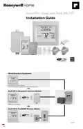
Home > Honeywell Home > Honeywell Home TH8320R1003-Uv VisionPRO 8000 with RedLINK Multistage Thermostat Installation Guide
Honeywell Home TH8320R1003-Uv VisionPRO 8000 with RedLINK Multistage Thermostat Installation Guide
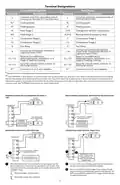

Terminal Designations
Conventional System
Heat Pump
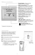
Description
Terminal
Description
Terminal
Common wire from secondary side of
cooling transformer (if 2 transformers).
Common wire from secondary side of
cooling transformer.
C
C
Rc*
R*
W
Cooling power.
Heating power.
Heat Stage 1
Rc
R
Cooling power.
Heating power.
O/B
AUX-E
Y
Changeover valve for heat pumps.
Backup Heat/Emergency Heat
Compressor Stage 1
Compressor Stage 2
Fan Relay
W2
Y
Heat Stage 2
Compressor Stage 1
Compressor Stage 2
Fan Relay
Y2
G
Y2
G
Connect to Compressor Monitor,
Zone Panel, Economizer Module or
Lighting Panel (TOD).
Connect to Economizer Module or
Lighting Panel (TOD).
A
L/A
Relay for humidification,
dehumidification, ventilation, or a
stage of heating/cooling.
Relay for humidification,
dehumidification, ventilation, or a
stage of heating/cooling.
U1 / U1
U1 / U1
Input for a wired indoor, outdoor or
discharge sensor.
Input for a wired indoor, outdoor or
discharge sensor.
S1 / S1
K**
S1 / S1
K**
Connect to K on C-wire adaptor.
Connect to K on C-wire adaptor.
* Remove factory installed jumper for two transformer systems.
** The THP9045 C-wire adaptor is used on heat/cool systems when you only have four wires at the thermostat and you would
like the thermostat to be powered with a common wire. Use the K terminal in place of the Y and G terminals on conventional or
heat pump systems to provide control of the fan and the compressor through a single wire—the unused wire then becomes your
common wire. See THP9045 instructions for more information.
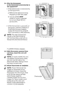
POWERED HUMIDIFIER, DEHUMIDIFIER OR VENTILA-
TOR
NON-POWERED HUMIDIFIER, DEHUMIDIFIER OR VENTILATOR
SYSTEM
TRANSFORMER
C
SYSTEM
TRANSFORMER
C
24
VAC
120
VAC
24
VAC
120
VAC
R
R
THERMOSTAT
C
THERMOSTAT
C
K
K
RC
R
RC
R
FIELD INSTALL JUMPER
BETWEEN R AND U1
HUM, DEHUM OR
VENT TRANSFORM-
ER
U1
U1
POWERED
HUMIDIFIER,
U1
U1
NON-POWERED
HUMIDIFIER,
24
VAC
120
VAC
DEHUMIDIFIER
OR VENTILATOR
DEHUMIDIFIER
OR VENTILATOR
DEHUMIDIFICATION WITH LOW SPEED FAN
CONNECTING A HEAT OR COOL STAGE TO U1
TRANSFORMER
TRANSFORMER
C
C
24 120
VAC VAC
24
VAC
120
VAC
THERMOSTAT
R
R
THERMOSTAT
C
C
K
K
RC
R
RC
R
FIELD INSTALL JUMPER
BETWEEN R AND U1
1
2
1
U1
U1
HEAT STAGE 3, COOL
STAGE 3, BACKUP HEAT
STAGE 2 FOR HEAT
U1
U1
OR
DEHUMIDIFICATION
WITH LOW SPEED FAN
PUMPS, OR GEOTHERMAL
RADIANT HEAT
Wire the thermostat U1 terminal to the low speed fan for
dehumidification control at the equipment as shown. The
relay can be set to normally open or normally closed in the
installer setup.
1
2
U1 terminals are normally open dry contacts when
set up for a stage of heating or cooling.
1
You must install a field jumper if the stage of heat-
ing or cooling is powered by system transformer. Do
NOT install a field jumper if the stage of heating has
its own transformer.
Normally open, dry contacts
Normally closed, dry contacts
5
| General | Details |
|---|---|
| Name | Honeywell Home TH8320R1003-Uv VisionPRO 8000 with RedLINK Multistage Thermostat Installation Guide |
| Make | Honeywell Home |
| Language | English |
| Filetype | PDF (Download) |
| File size | 0.64 MB |


Honeywell Home TH2110DH 1 Cool Programmable Digital Thermostat Installation Guide

Honeywell Home DT4R Wireless Room Thermostat User Guide

Honeywell Home N100 Series Non Programmable Thermostat User Guide

Honeywell Home X1N Non Programmable Thermostat Installation Guide

Honeywell Home DT4M Wired Room Thermostat User Manual

Honeywell Home T834 Series Thermostat Owner’s Manual

Honeywell Home M38794 T10 and T10 plus Pro Smart Thermostat with RedLINK Installation Guide

Honeywell Home DT4 Channel Wired Room Thermostat Instruction Manual

Honeywell Home T10 Smart Home Thermostat Instructions

Honeywell Home FocusPRO Smart S200 Series Smart Thermostat User Guide


Danfoss RMT-230 Room Thermostat Installation Guide

Danfoss KP 61 Temperature Switches Thermostat Installation Guide

Honeywell TH5220D1003 Heater Thermostat Owner’s Manual

htc HYT001 WIFI Digital Heating Thermostat User Manual

PURGEAR STC-2303 Digital Thermostat User Guide

EMOS P5683 Surface Mount Thermostat Instructions

SILVERCREST IAN 469312_2310 Digital Radiator Thermostat Instruction Manual

Network Thermostat X7C-WIFI Smart Touchscreen Thermostat Instruction Manual

Danfoss ECtemp 132 Electronic Thermostat Installation Guide

HYSEN HY02DB-WIFI Wifi Plug In Thermostat User Manual